I don’t think I had ever heard of an EFHW (End-fed half wave) antenna 5 years ago. Now they seem to be in use everywhere. They are a compromise multi-band antenna, but they seem to work well enough that people use them.
In a follow-up email exchange, Ward Silver, N0AX, provided this information on the EFHW that was new to me.
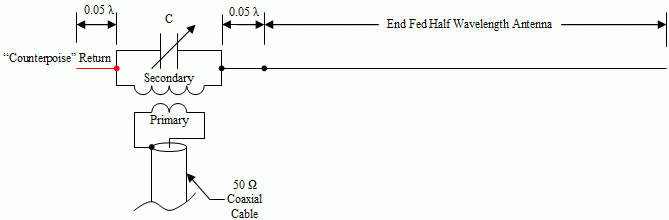
The key to getting the most out of an EFHW is the impedance transformer and how you install the antenna.
Transformer design was all over the place until K1RF published a really good presentation on his effective design. (http://gnarc.org/wp-content/uploads/The-End-Fed-Half-Wave-Antenna.pdf) Summarizing, you have to use the right ferrite and have an end-fed impedance that is reasonably close to what the transformer can be expected to match. The ferrite has to be in its inductive (low-loss) region because it’s a flux-coupled transformer, not a transmission-line choke. Type 43 works well across the HF spectrum, becoming lossy above low VHF where it is used for EMI suppression. Using Type 31 makes the transformer an RF sponge at HF which is what it’s designed for. Turns ratios making the impedance ratio anywhere from 9:1 (3 to 1 turns) to 81:1 (9 to 1 turns) are used but the ratio most suitable to a wide variety of feed point impedances is 49:1 as I explain here: https://www.onallbands.com/feeding-end-fed-antennas/ Not having enough core cross-section area for the power level involved (1.5″ OD for QRP, 2.4″ OD for 100W, 2×2.4″ OD for up to 500 W CW or 1 kW SSB, 3×2.4″ OD for 1.5 kW) drives the core into a lossy region and it heats up.
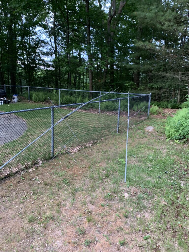
Having some additional conductor beyond the feed point – I hesitate to call it a “counterpoise” because that’s not what it is acting as – helps stabilize the feed point impedance. This is usually the outer surface of the coax. Using a current choke at the feed point blocks this path and makes the feed point impedance erratic so it’s kind of a crapshoot how the SWR will look. If the feed point transformer is up in the air, such as in a horizontal configuration, the length of coax starts to become more significant and the antenna starts to look like an OCFD. Depending on how much coax surface there is, the resulting feed point impedance can also become erratic. The most reliably effective installation is to put the transformer three to six feet above the ground, run the wire straight up with a non-metallic (fiberglass) mast for at least 10 feet, then run the wire up to the highest point you can find so that it’s basically an inverted-L. Just lay the coax on the ground – it will be fine and non-fussy.
True, the EFHW only “requires” one support, but so does a dipole as an inverted-V or sloping dipole. The important thing is where the current maxima are located with respect to ground. This changes with frequency. On the lowest two bands, the current maxima are in the middle half of the antenna. On the higher bands, the current maxima are all across the antenna with the higher peaks nearer the transformer. The higher the maxima above ground, the more efficient radiator the antenna will be. On 15/12/10 meters, an 80-10 antenna starts to look like an end-fed long wire and radiates in the direction away from the feed point.
A center-fed doublet will work just as well but you have to have an antenna tuner for the even harmonic bands and use a low-loss open-wire line between the feed point and the tuner. Note that using 100 feet or more of RG-58 with the “wrong” transformer or a funky installation will make an antenna look just dandy to the transmitter due to feed line loss. If the coax-fed EFHW is presenting an SWR high enough to require a tuner at the transmitter, something is wrong either in the design or installation. You may be able to get a match with the tuner but feed line loss is likely to be high – you can hear people but not work them.
Most folks don’t really understand the antenna, install it any old way or really low, have unreasonable expectations, and are disappointed. Or the manufacturer doesn’t use the right ferrite or provides the wrong impedance ratio, or, or, or and the antenna just isn’t efficient. The result is unhappy customers who need education – sometimes “app notes” will really help.
Ward Silver, N0AX, email dated June 26, 2024
I found the information above informative and asked Ward if I could share it so others might benefit. Hope you find something that helps you get the most out of your EFHW antenna.
I have been using a Hygain TH7DXX as my south antenna ever since I built the station in 1993. It has served me well, but some years ago the SWR on 15m started being a problem. I could still work people, but having an SWR of more than 2:1 bothered me. No amount of changing things seemed to make it better.
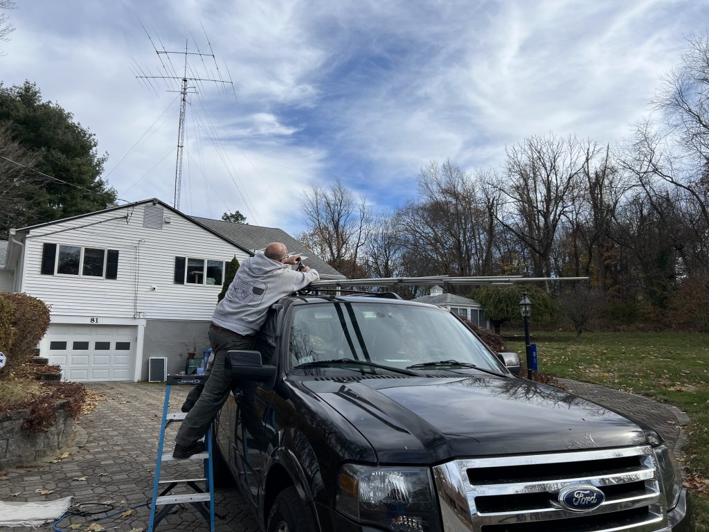
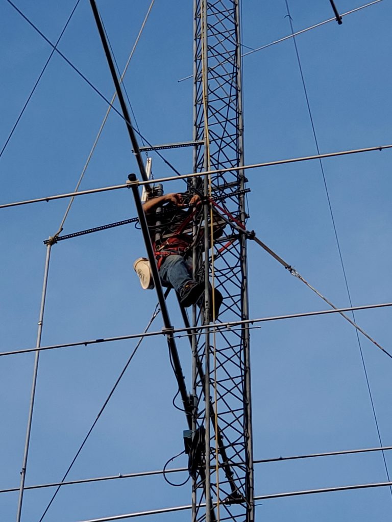
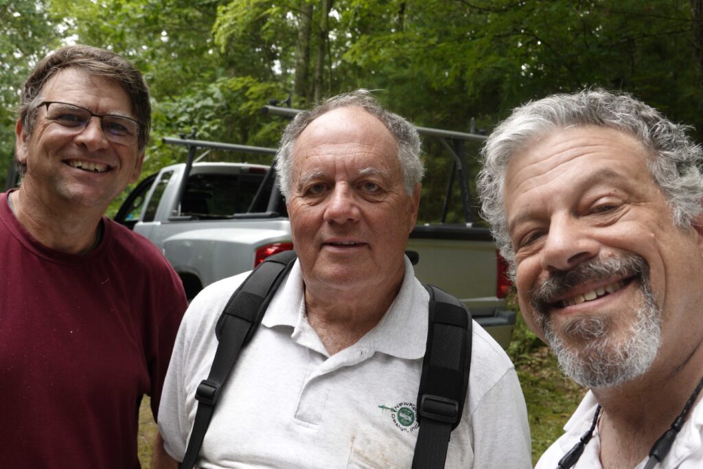
In November 2023, Pete W1RM posted a message that he was looking to sell a C31xr that he had recently replaced with a JK tri-bander. I jumped on it.
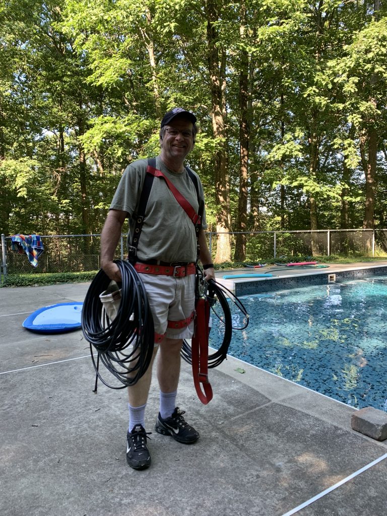
Mark KW1X and I drove down to Pete’s place in CT to pick up the antenna on November 15. You can see Pete’s new antennas in the background.
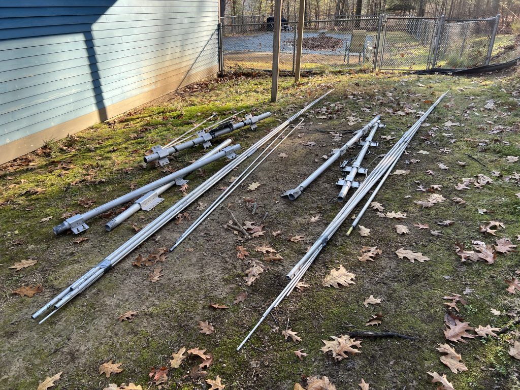
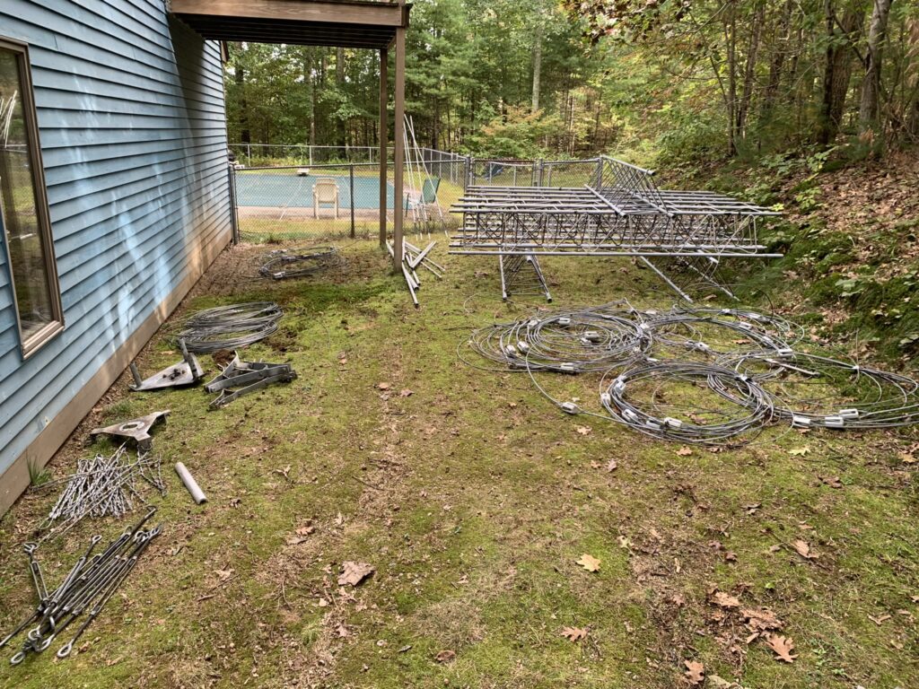
Here is the complete kit as it arrived at my place.
It was now 2 weeks before CQ WW CW and I was determined to get this antenna in the air before then. The first step was to haul all the pieces up the hill and start assembling.
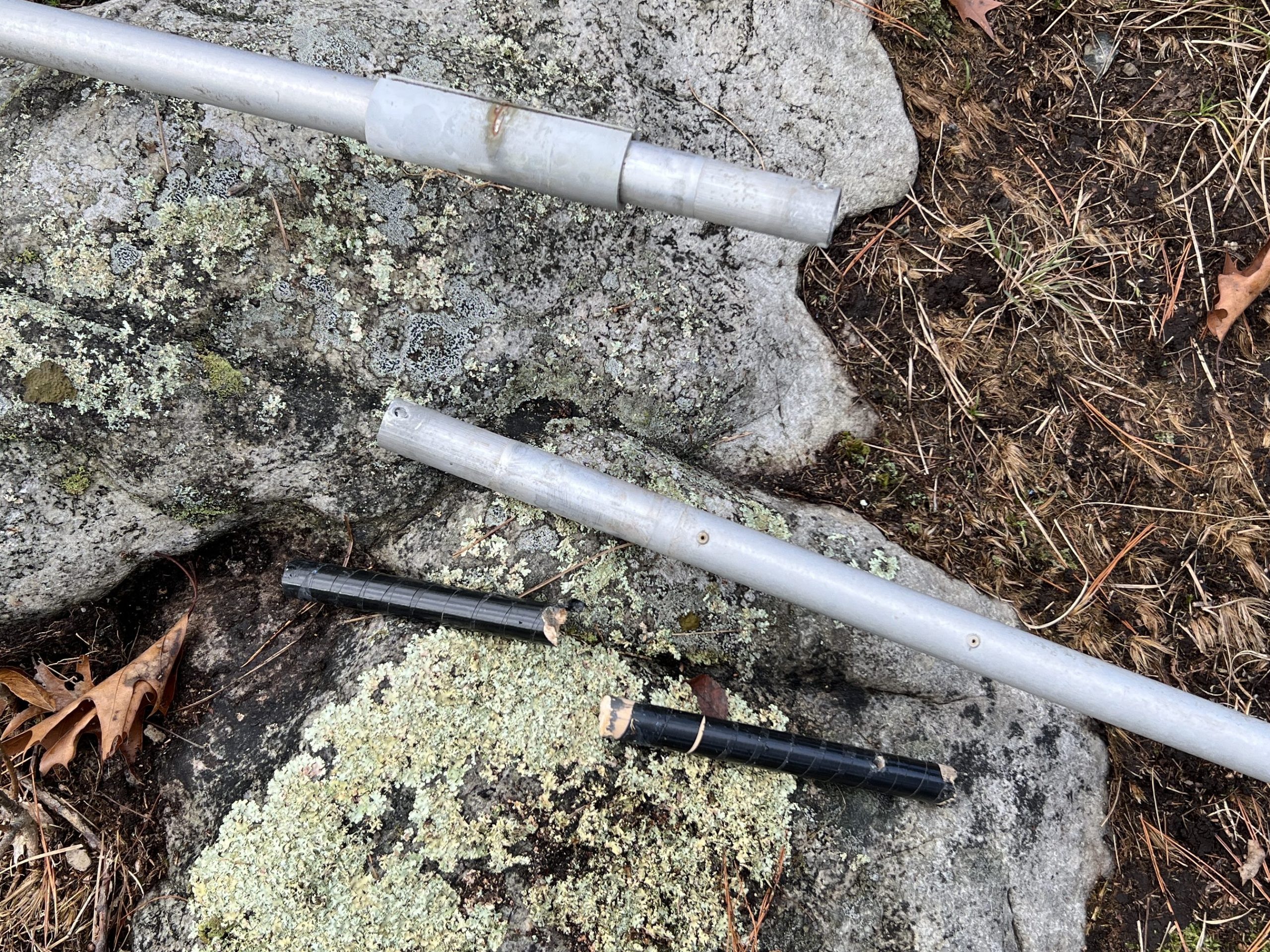
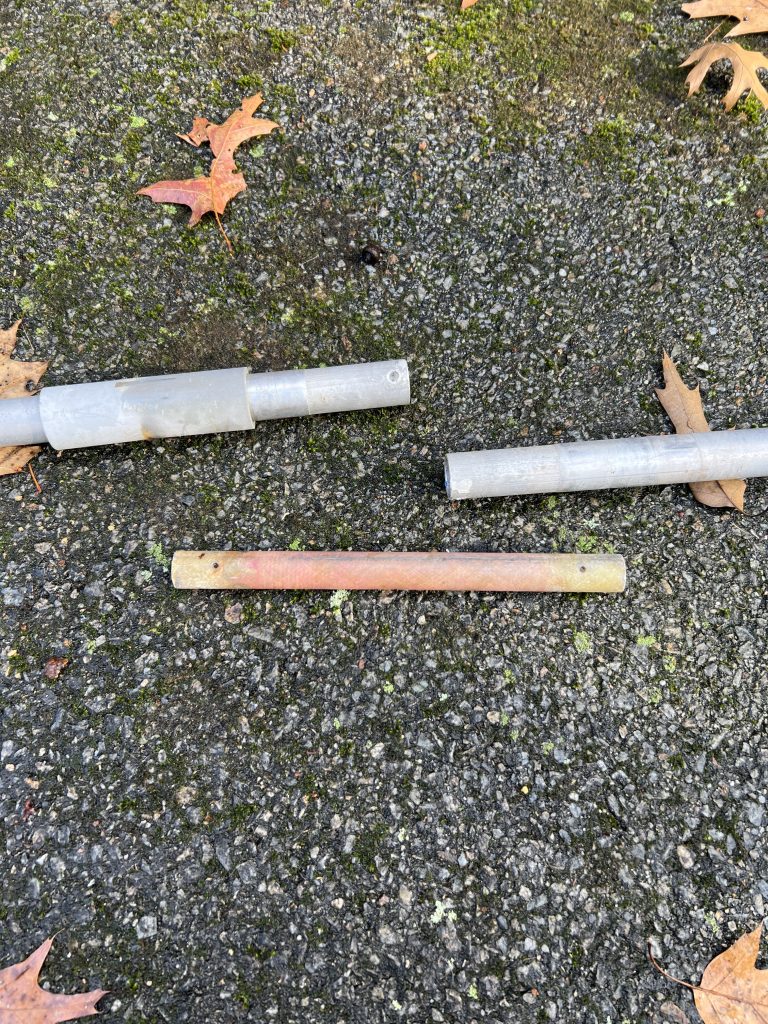
Some of the driven elements use a non-metallic spacer to isolate the element halves. As I put things together, I realized that I was missing one of them. I didn’t have much time so I tried to use a wooden dowel. It couldn’t handle the stress and quickly failed.
I had some extra loading coils left over from rebuilding the 40-2CD stack in 2022. Amazingly, one of the fiberglass rods that make up the coil was a perfect fit! It definitely had the required strength.
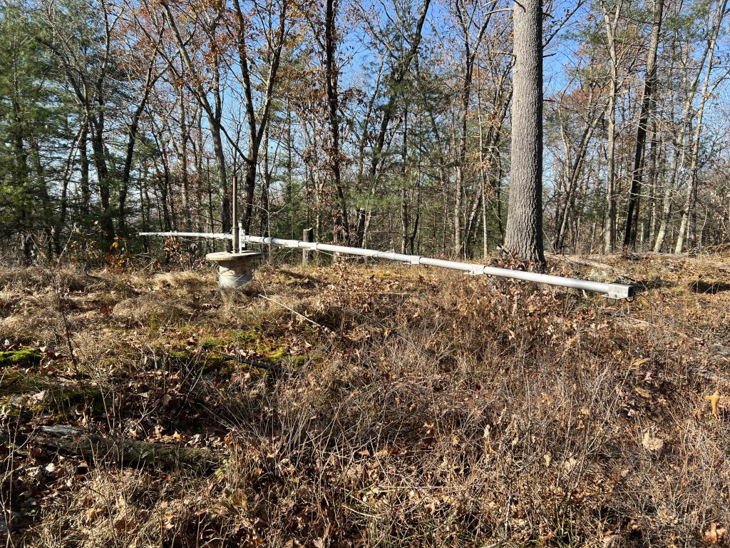
Antenna assembly went quickly once that disaster was averted.
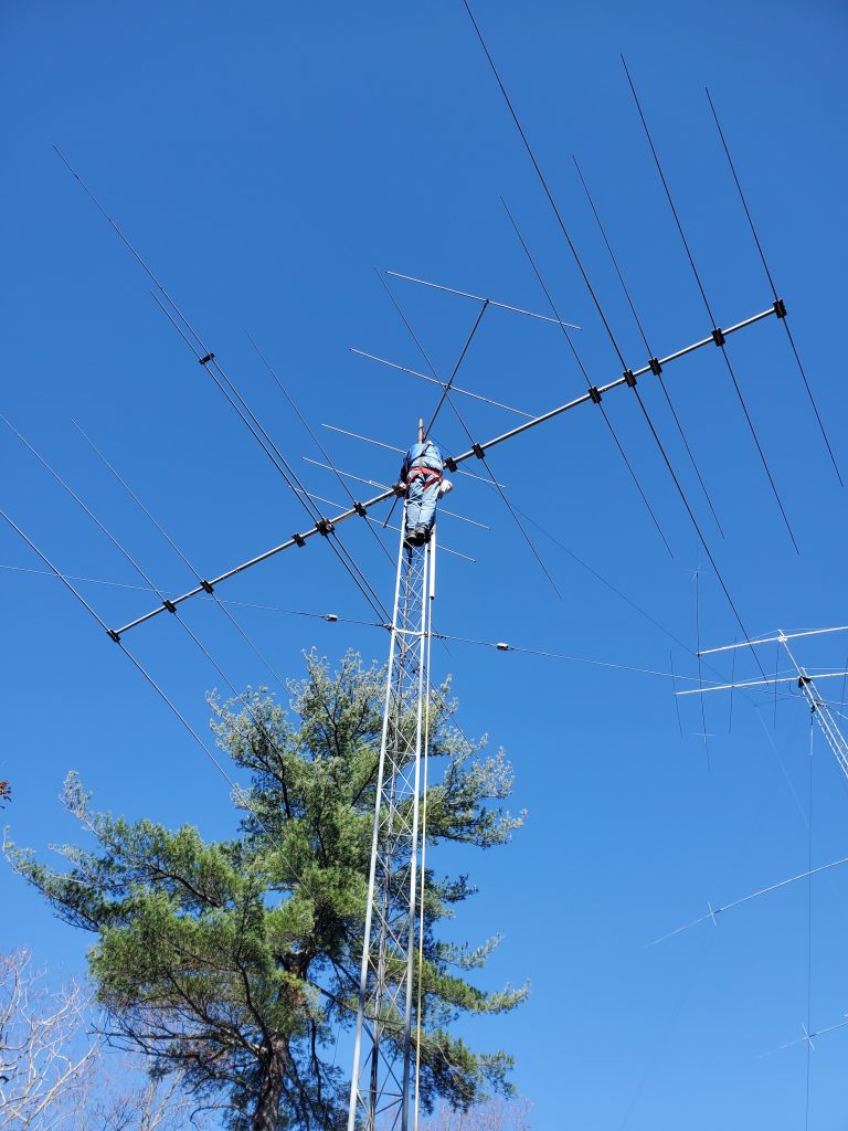
I did not truly appreciate how big this antenna was until I started to assemble it. Long boom, lots of elements (14!), and a total weight of over 85 pounds. I started to worry if it was going to bump into the trees that surrounded the tower (it did).
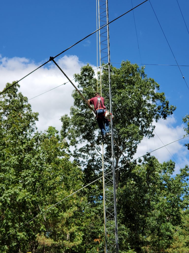
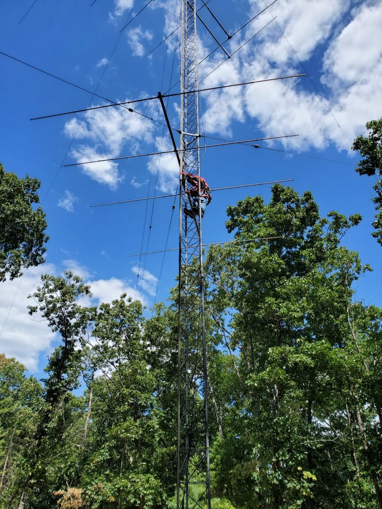
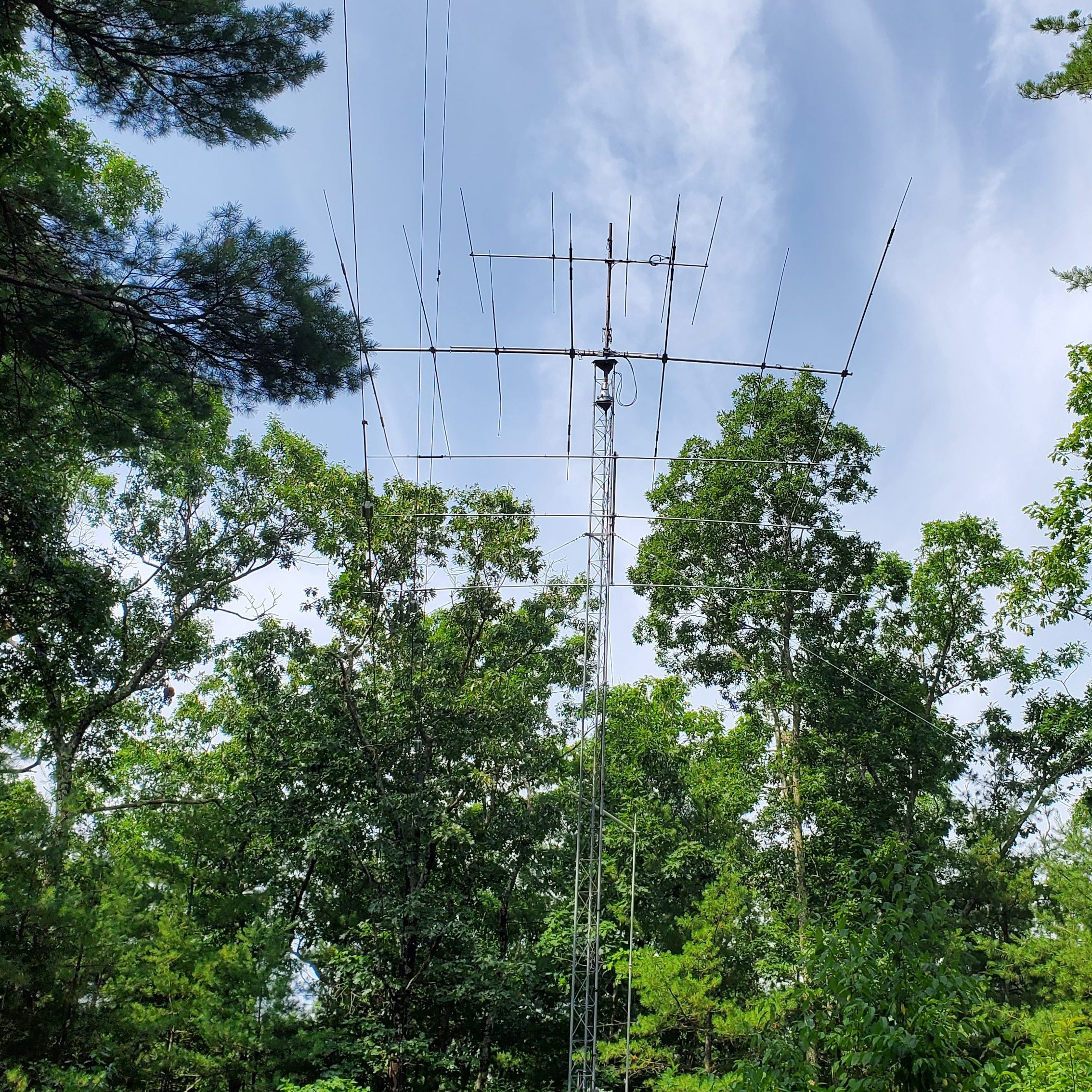
Mark KW1X and Martin AA1ON came over to help with removing the TH7 and putting up the C31. Here is the TH7 before removal.
With the help of gravity, we had no problem bringing the TH7 down the tower. This 40′ tower only has one set of guy wires at the 30′ level so it was not difficult to corkscrew the beams around the guy wires. The C31xr was heavy and it took all of Mark and Martin’s effort to pull it up.
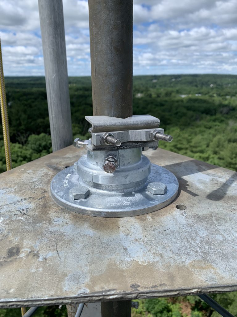
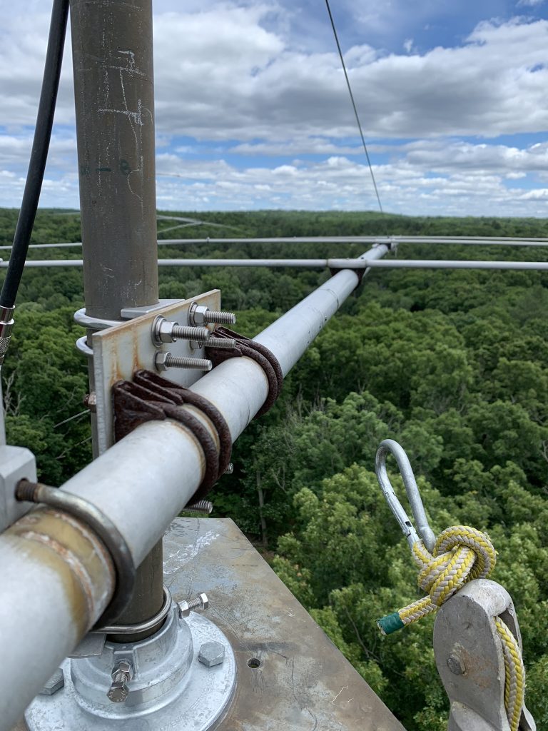
I was happy when the U-bolts were in place and the antenna was attached to the mast.
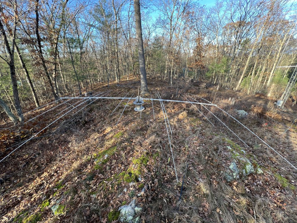
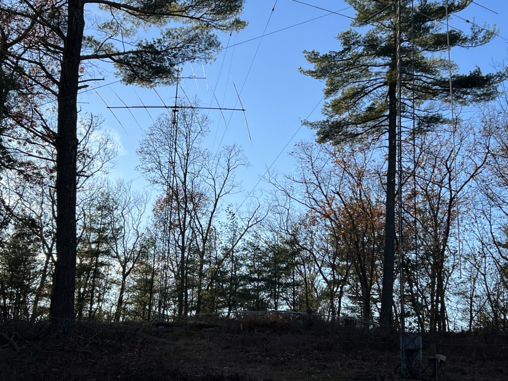
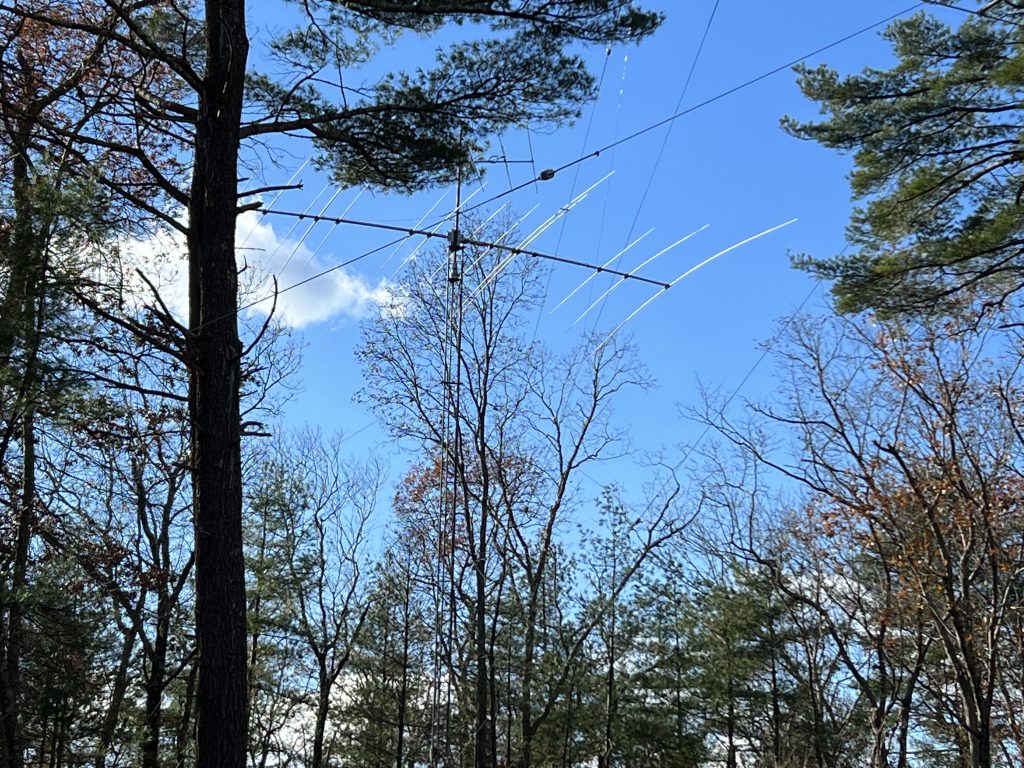
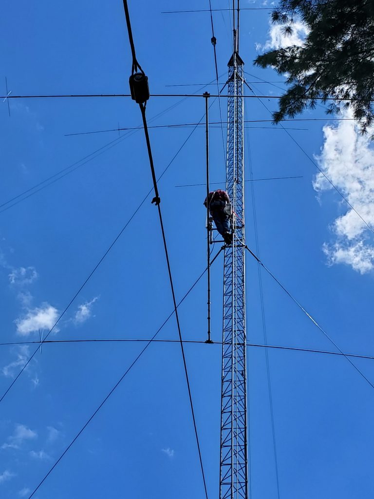
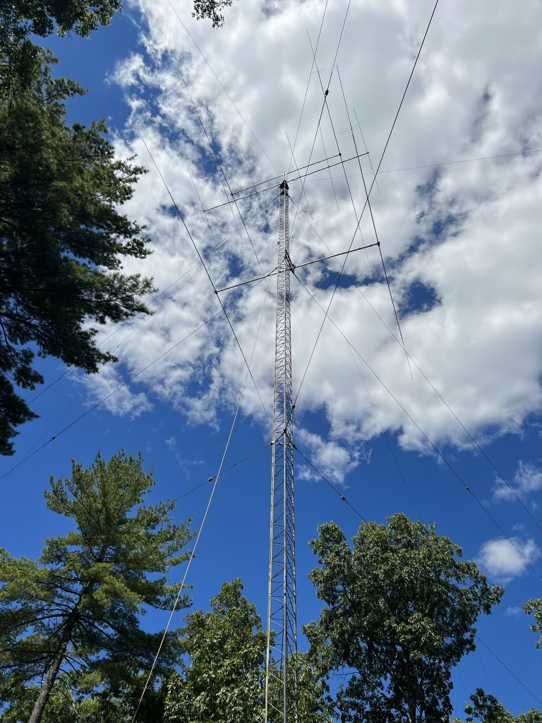
Here is the first look once I was back on the ground.
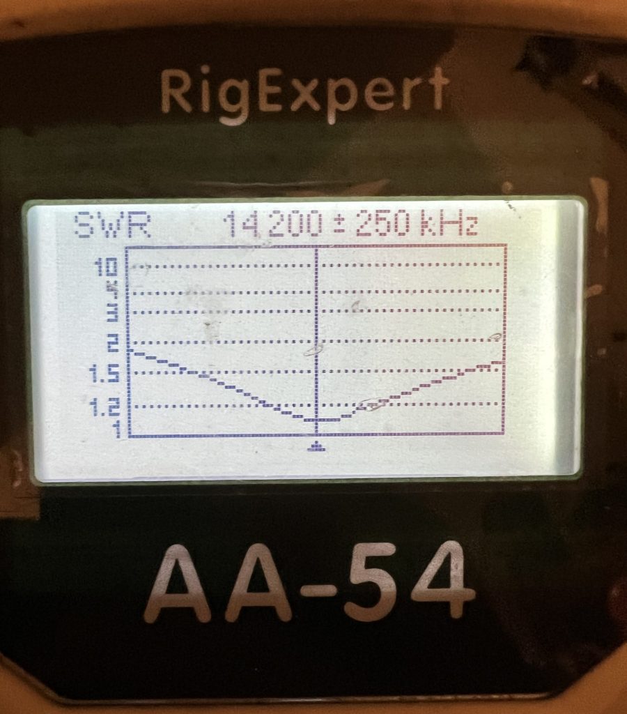
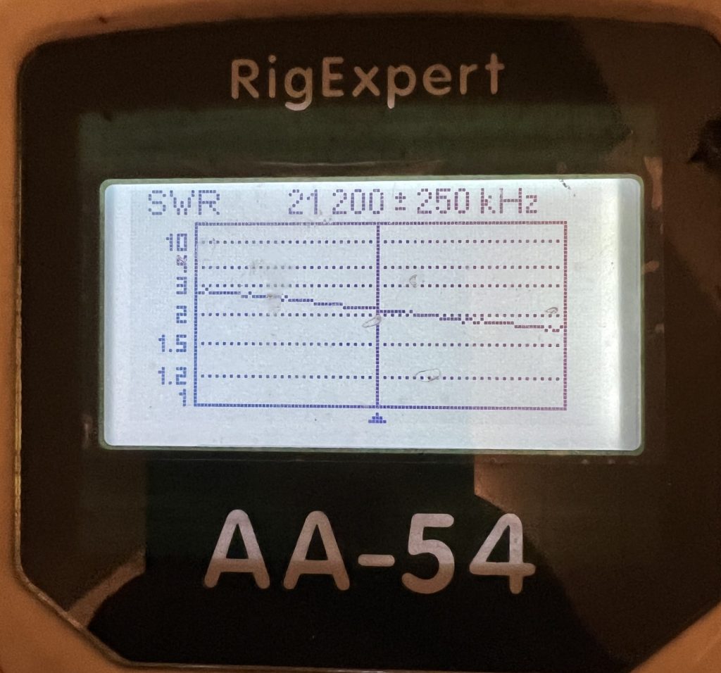
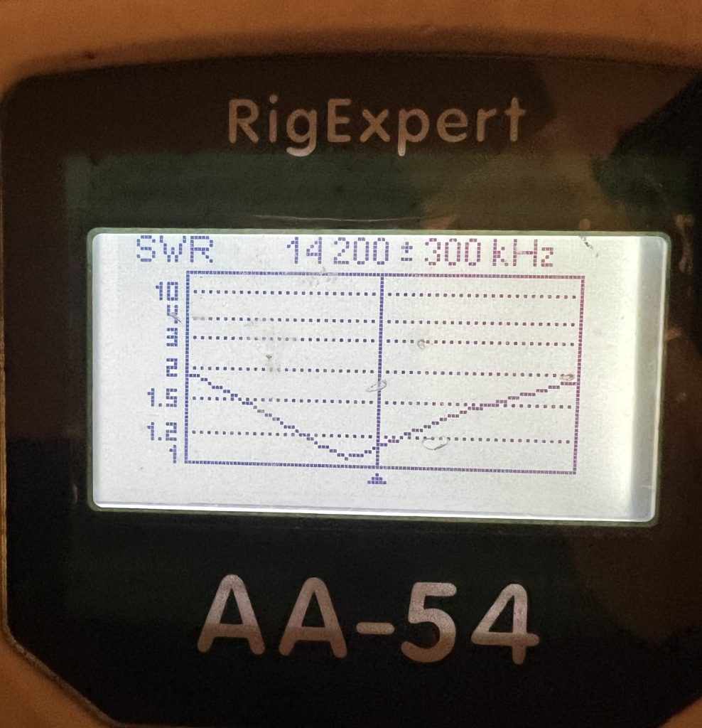
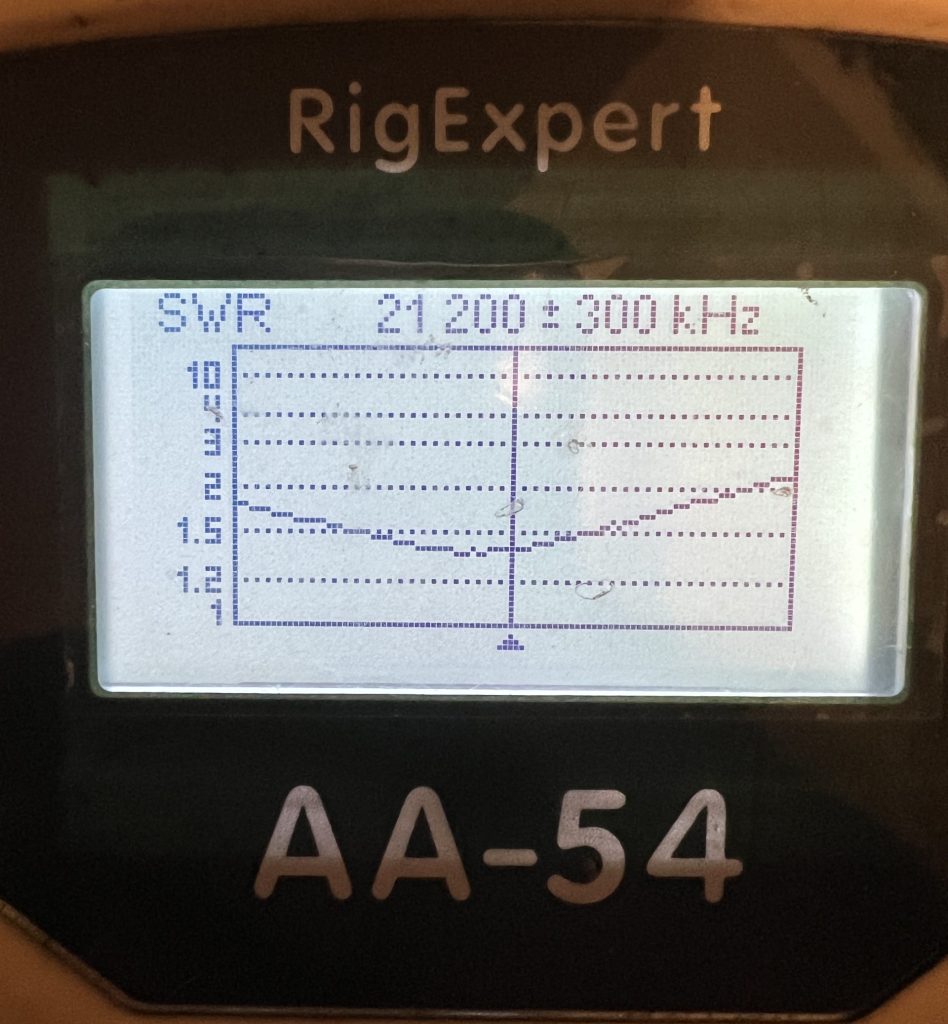
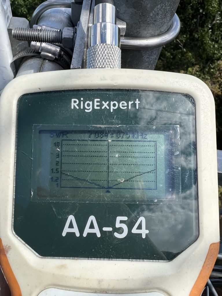
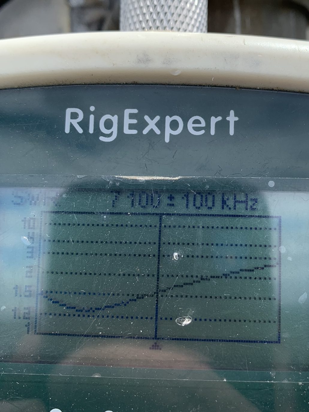
The next step was to check the SWR. Hmmm… not what I expected.
Discussion with W2GD and others who had a C31 indicated that having problems with 15m was not unusual. The first suggestion was to manipulate the loading coil.
I had put the antenna up with the coil the same as it was when at W1RM. The coil had the turns taped together.
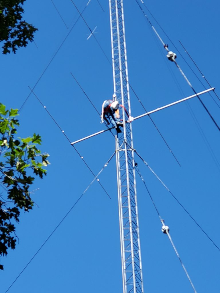
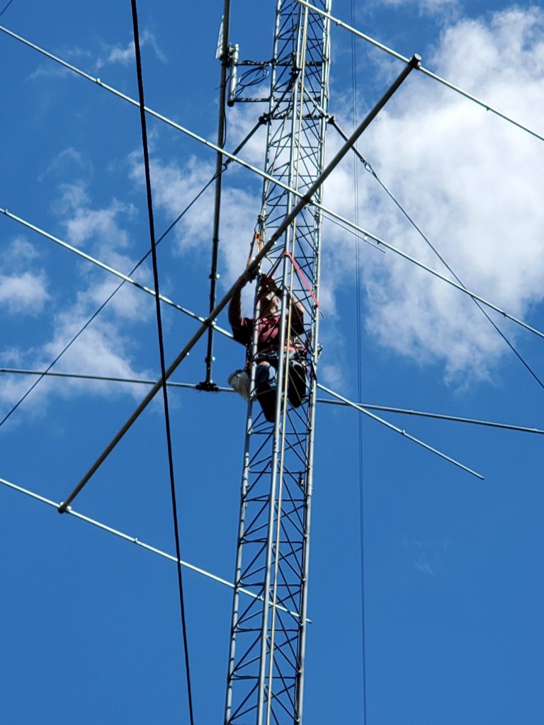
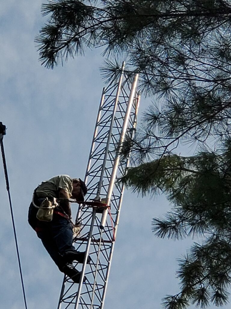
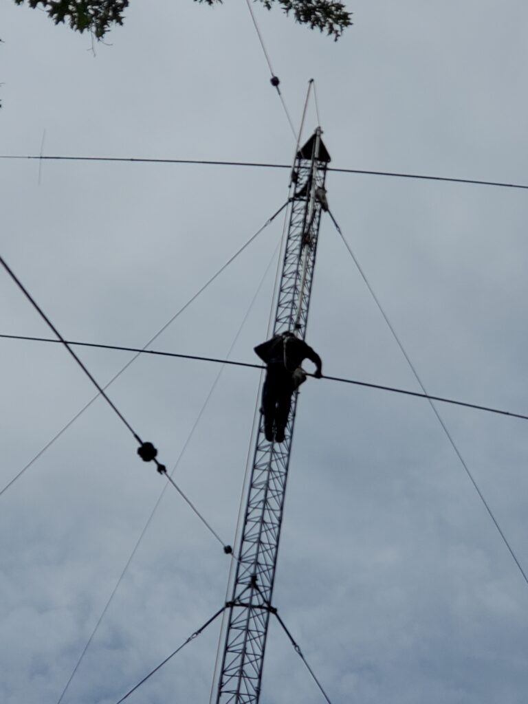
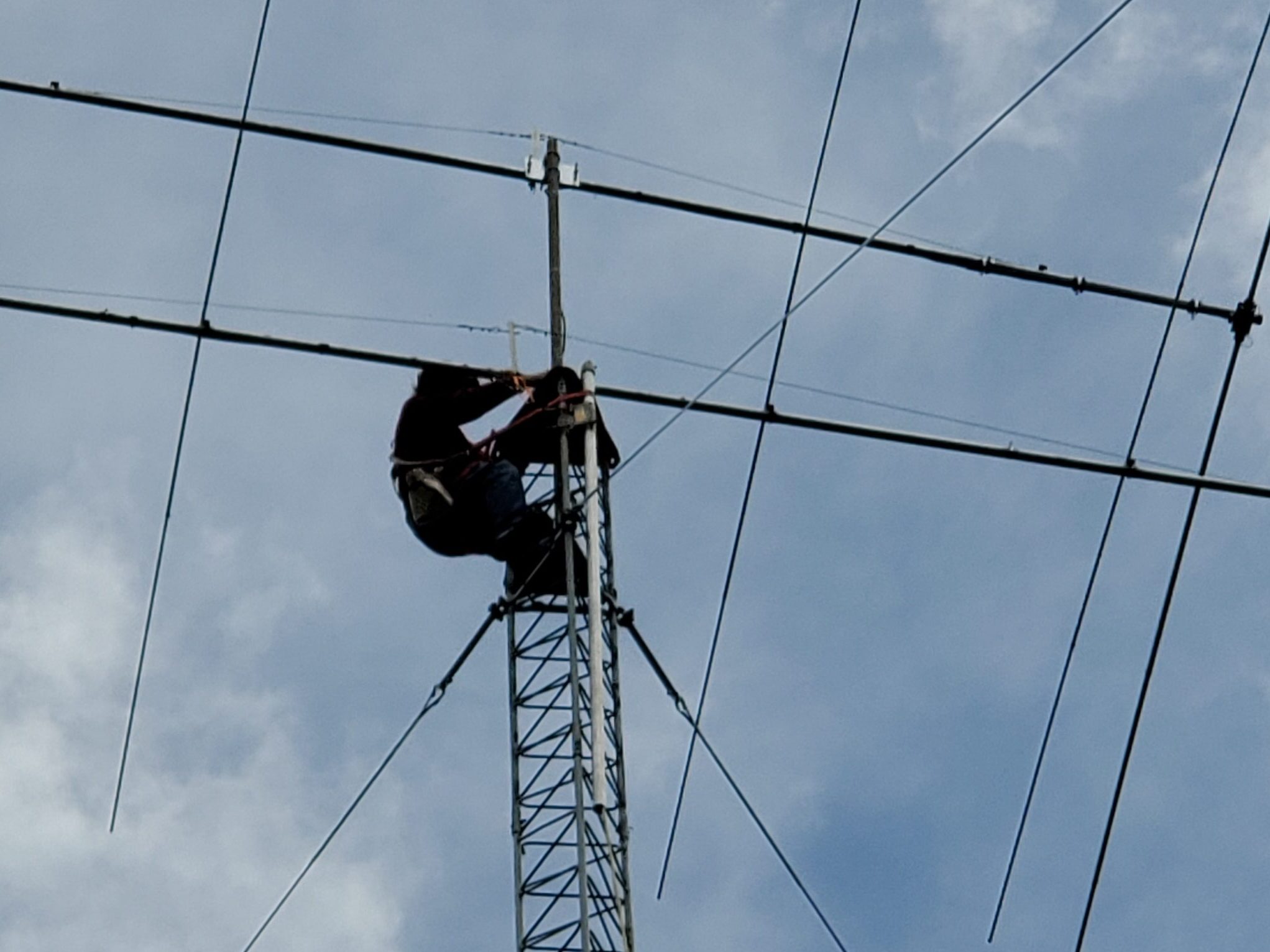
Luckily, I could just reach the coil from the tower. So on Thanksgiving morning (Thu before CQWW) I removed the tape and spread out the coil.
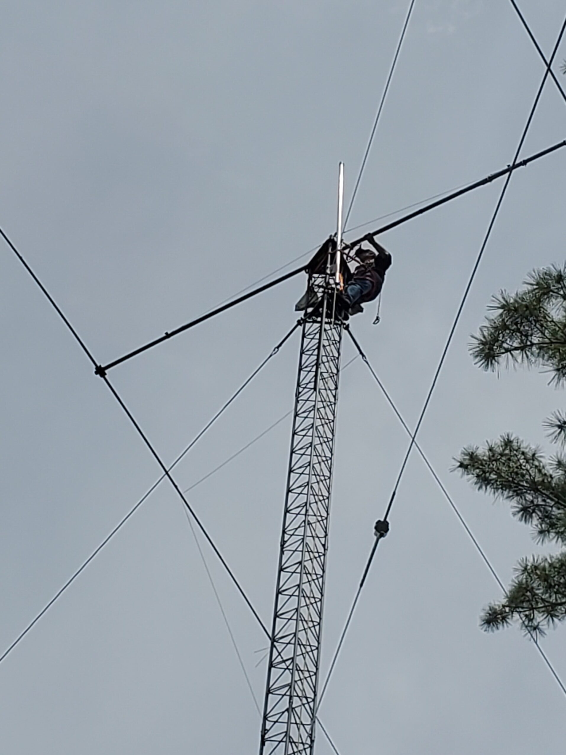
Another suggestion to move the SWR minimum on 15m down the band was to make the shorting jumper on the 15m element a bit longer. This was much more difficult to reach and involved holding the jumper in place while screwing on a small nut. I was scared I was going to drop the nut and never find it! I did manage to get it on and tightened up. You can see the jumper to the left of the coil.
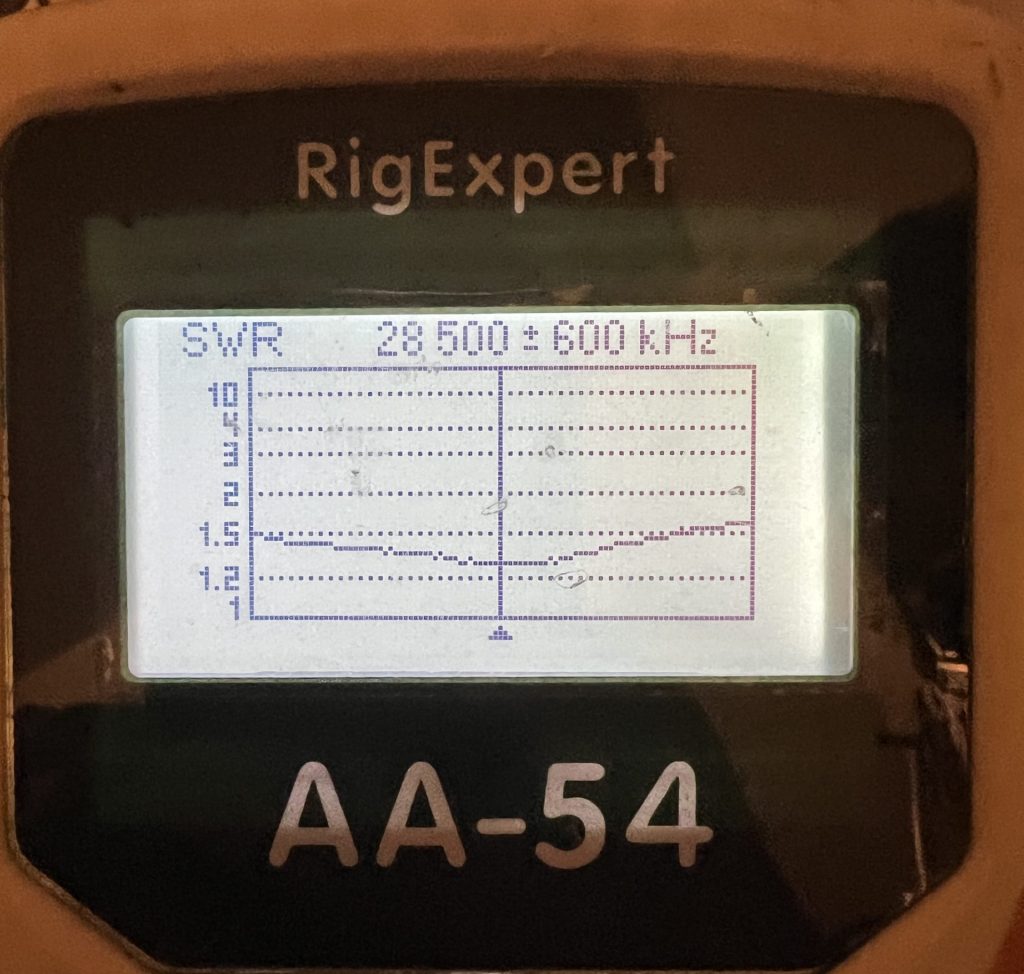
I was relieved and happy when I saw the results.
Mission accomplished! A bit of work with a rope saw cleared the tree branches that impacted the turning of the antenna and it was ready for action.
The antenna worked great during CQ WW CW. Having a 7-el 10m Yagi for a multiplier chasing antenna was nice even though it meant a lot more activity for the rotator.
One can’t really use NEC (even NEC4) to re-optimize this in a way that you could be sure that your new dimensions (keeping the spacing the same, which you can’t easily move) will yield an accurate real world result. The reason being is that NEC can’t handle elements this close together – mainly the 20m driven and 15m parasitically coupled driven element.
It’s not that it probably can’t be improved (mainly I mean the 15m SWR), but it can’t easily be done by working up a remodel via NEC like you normally would. On tribanders like this, you must keep the driven elements at least 18 inches or so from one another to keep from stressing the NEC model accuracy. That said, I believe there is an empty element bracket further back (towards the reflector) and if it was me, I’d move the 15m to that one, string a phasing line across the three driven elements and feed the 20 meter element instead. You could probably work up something a bit better that way, design it all for 50 ohm (get rid of the hairpin).
Randy Thompson K5ZD and Tom Georgens W2SC went to Bologna Italy with every intention to win the World Radiosport Team Championship. Despite their best efforts, they fell short but not by much. They ranked 8th out of 58 teams with an overall score of 5,945,800 points which included 4390 QSOs in 24 hours. Randy talks in detail about qualifying, selecting the right teammate, prepping for their operating station, redundancy, location surprises, and contest tactics. If you’re into ham radio contesting, you’ll enjoy hearing from this contest hall of famer and now repeat WRTC competitor.
I had the pleasure of being interviewed by Kevin Thomas W1DED. It was a wide-ranging conversation about what makes contesting fun and interesting to me.
Contesting Tips and Inspiration from Hall of Famer Randy Thompson K5ZD
If you’re new to contesting or just want to get some inspiration and tips from one of the best contesters in the world, you may want to watch this video interview with Randy Thompson, K5ZD. Randy has been contesting for 50 years and was inducted into the CQ Contest Hall of Fame in 2008. He recently participated in the ARRL DX SSB Contest where he is currently (and unofficially) ranked third worldwide in the Single Operator Unlimited All Band High Power category. He racked up over 4.4 million points while also taking care of some household errands, taking his wife out to dinner, and watching some Formula 1 racing. Randy also operated remotely, for the first time, with the multi-op ZF1A entry in CQ WPX SSB 2023. You’ll be impressed with Randy’s cool, measured approach to amateur radio contesting and his focus on keeping up with the ever-changing game with a positive attitude.
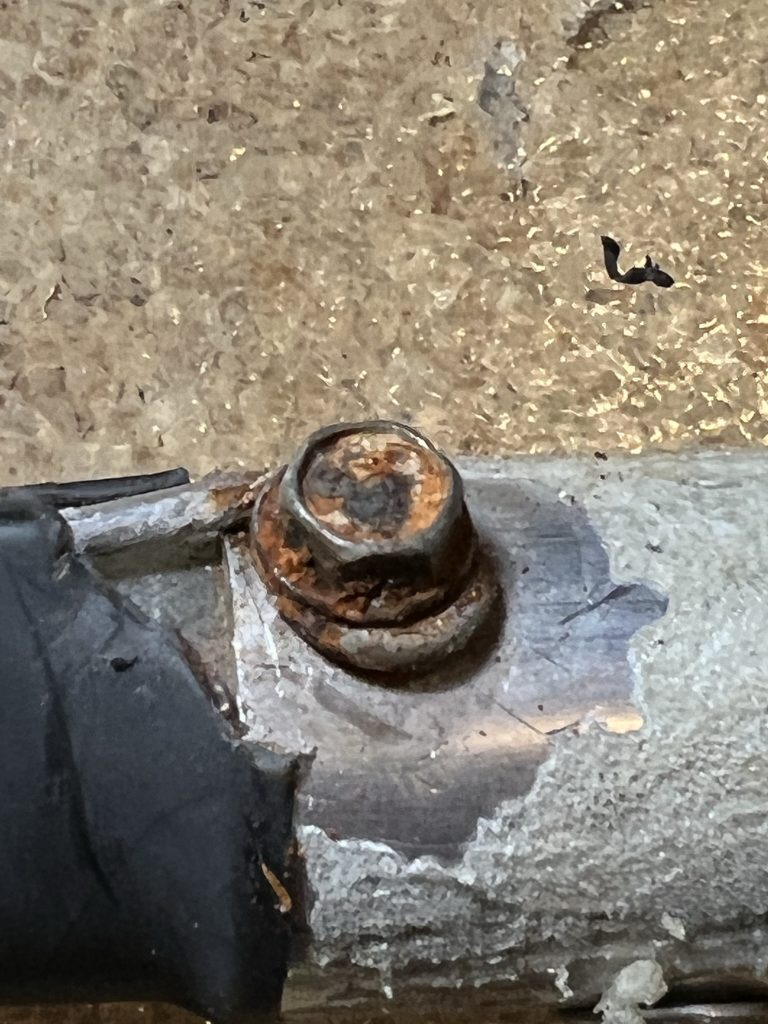
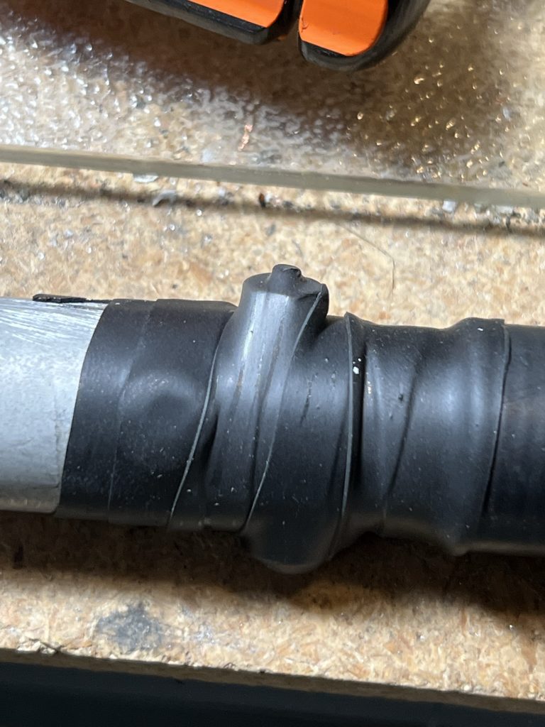
The Cushcraft 40-2CD and XM-240 use identical loading coils on the driven and reflector elements to help shorten the overall element length. The original design of the loading coils used a sheet metal screw to attach the wire coil to the aluminum element. Even though it is covered by heat shrink tubing, it becomes a point of failure when the sheet metal screw begins to corrode.
I recently rebuilt two 40-2CD antennas and had the need to renew the loading coil connections.
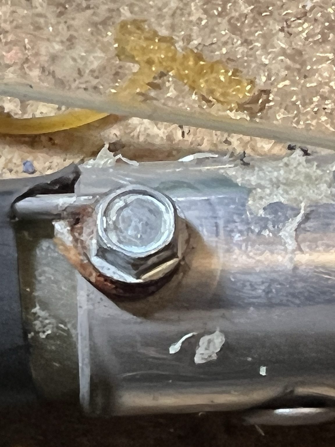
View of a corroded sheet metal screw when the heat shrink is removedAnother sheet metal screw that is in better condition
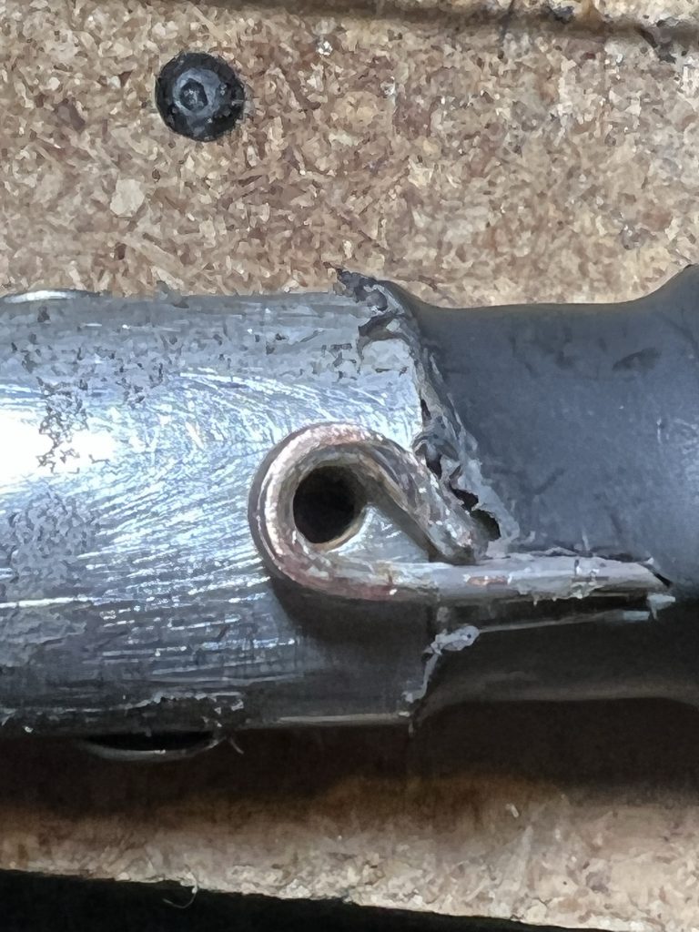
The first step is to remove the screw and clean everything up.
Element and wire cleaned
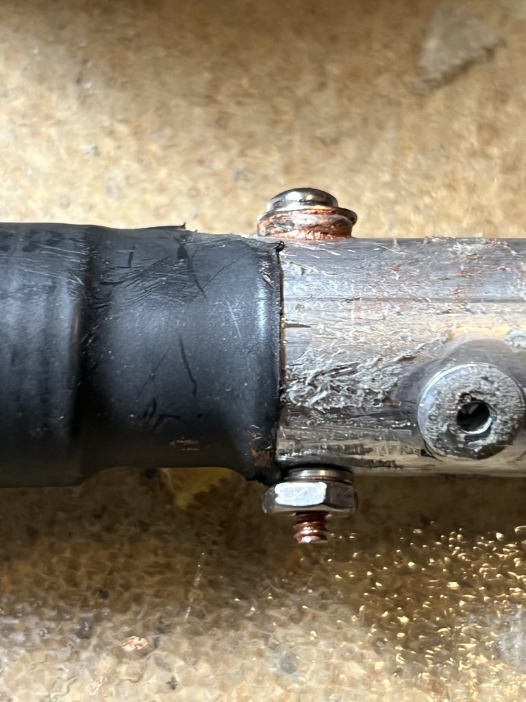
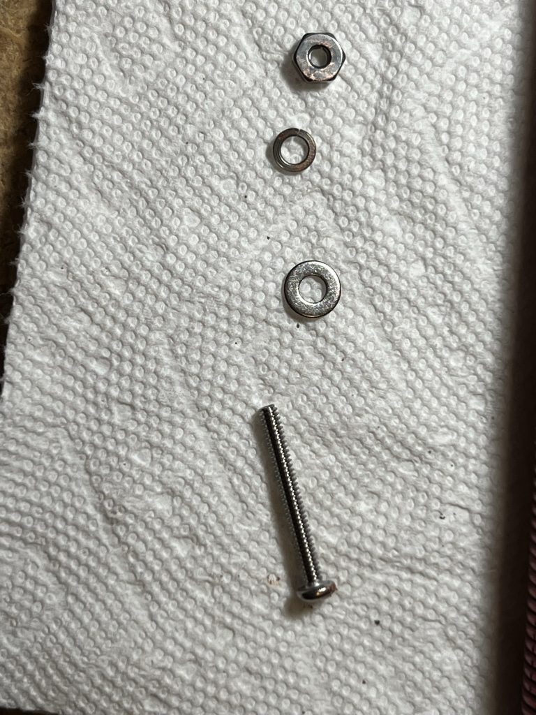
Drill a hole through the element. This will allow use of a stainless steel nut and bolt for a much more secure connection. I used a washer to help hold the wire. Also applied a dab of SS Jet-30 to improve conductivity.
New stainless nut and bolt attachment
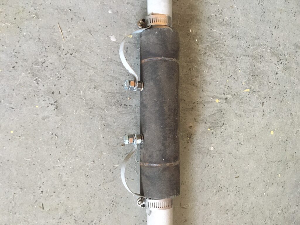
I then used some rubber liner tape to wrap the connection point to make it as waterproof as possible.
Tape over the connection to make as waterproof as possible
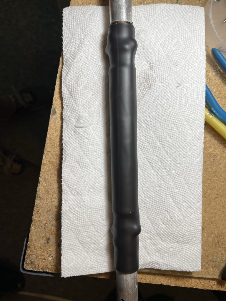
I then used some 1.25″ heat shrink tubing to cover the complete loading coil.
Heatshrink tubing covering the loading coil
Simply repeat this process for each loading coil. This small effort will prevent a common failure point for the 40-2CD antenna.
Sorry I didn’t record all the part sizes that I purchased at the local hardware store, but here they are in a photo.
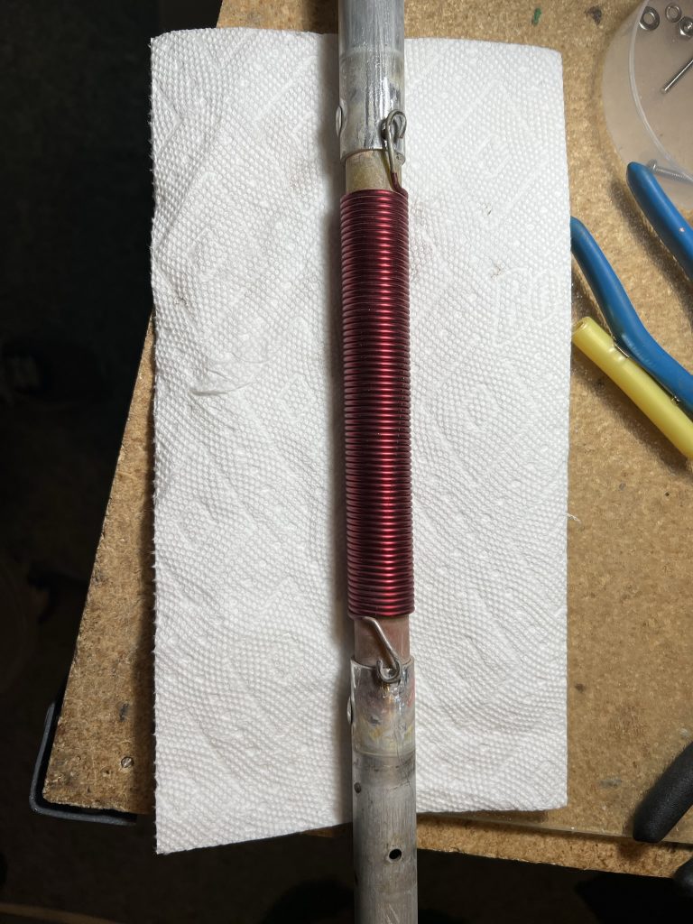
For reference, here is a loading coil with all of the shrink wrap tubing removed.
This is a continuation of the story of my project to replace one of my ham radio towers. Read part 1 first.
July 23, 2022
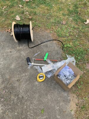
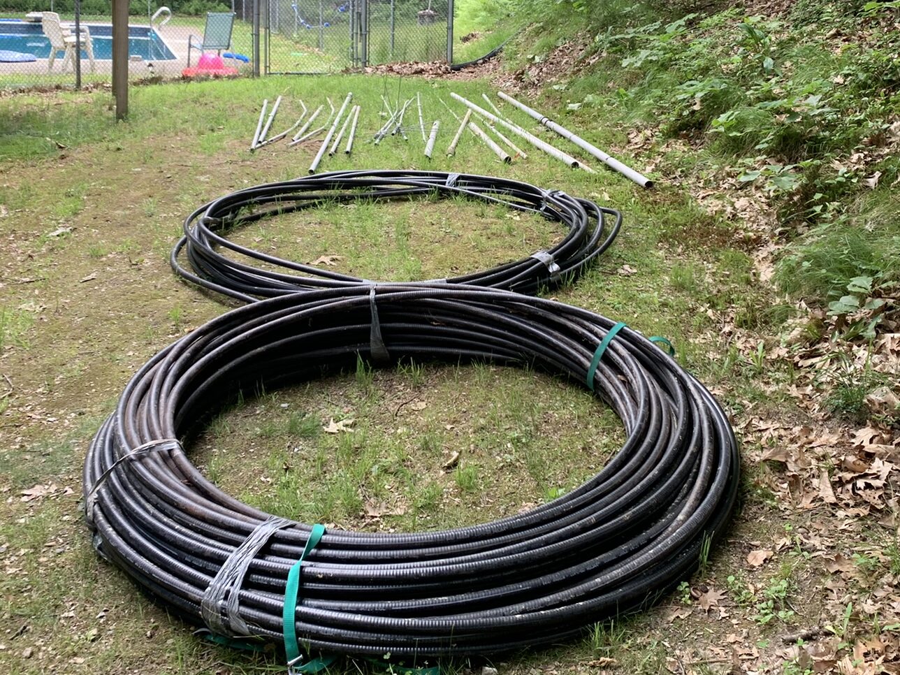
I got a great deal on some LDF5-50A 7/8″ hardline. It arrived in two pieces, but as luck would have it, they were both perfect for what I needed. The 240′ run got to the base of the new tower. The 290′ run got to the base of the tower with the TH7, A3WS, and 6m beam.
Needed connectors and found some on e-Bay. Minimal instructions. Finally found a manual from Andrews about installing connectors that filled in some of the gaps. Took me a few tries to figure out the proper way to install them. Hoping the hardline will provide a significant improvement in loss over the previous 75 ohm CATV feedline.
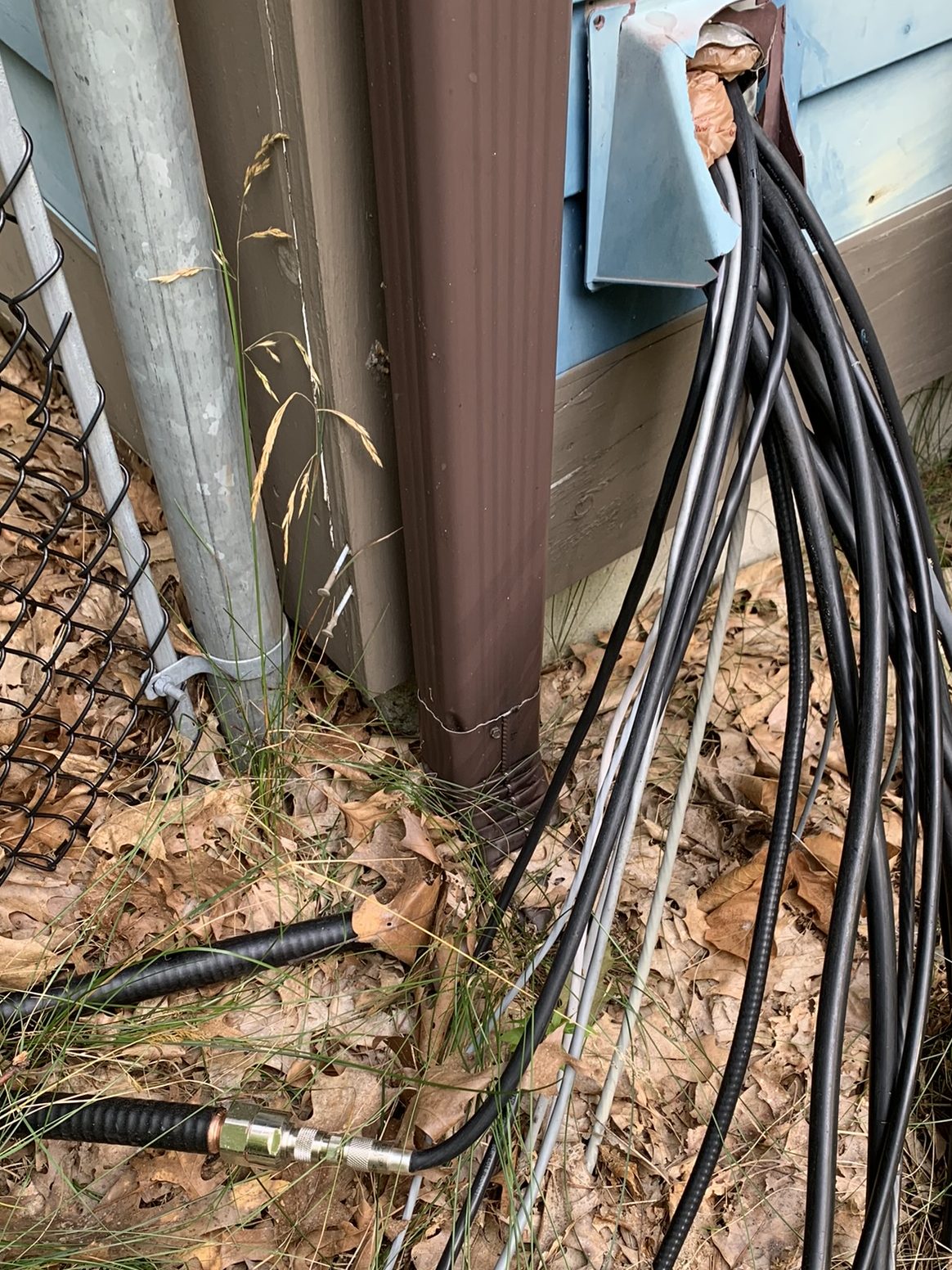
New hardline connector and cable entrance
July 24, 2022
I continued working on trying to convert the two and a half used 40-2CD antennas that I had on hand into the making of a new one. The biggest challenge is getting the driven element separated from the insulator (used a hammer), and getting the reflector and boom pieces apart.
Then I washed everything and started reinforcing per the W6QHS article recommendations. Having the extra element pieces was very helpful.
40-2CD parts staging after cleanup
August 13, 2022
Finally got all the bits and pieces together to make a complete 40-2CD with heavy-duty reinforcement. Assembled everything at the 5-foot level on the tower.
40-2CD #2 ready to go
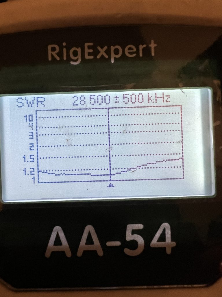
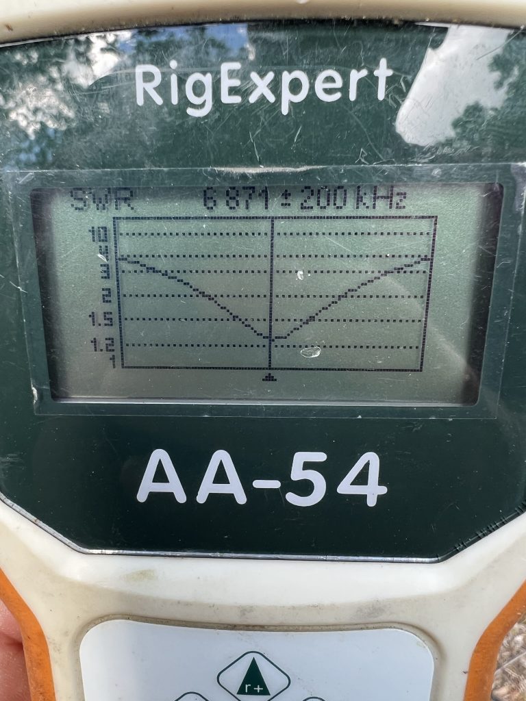
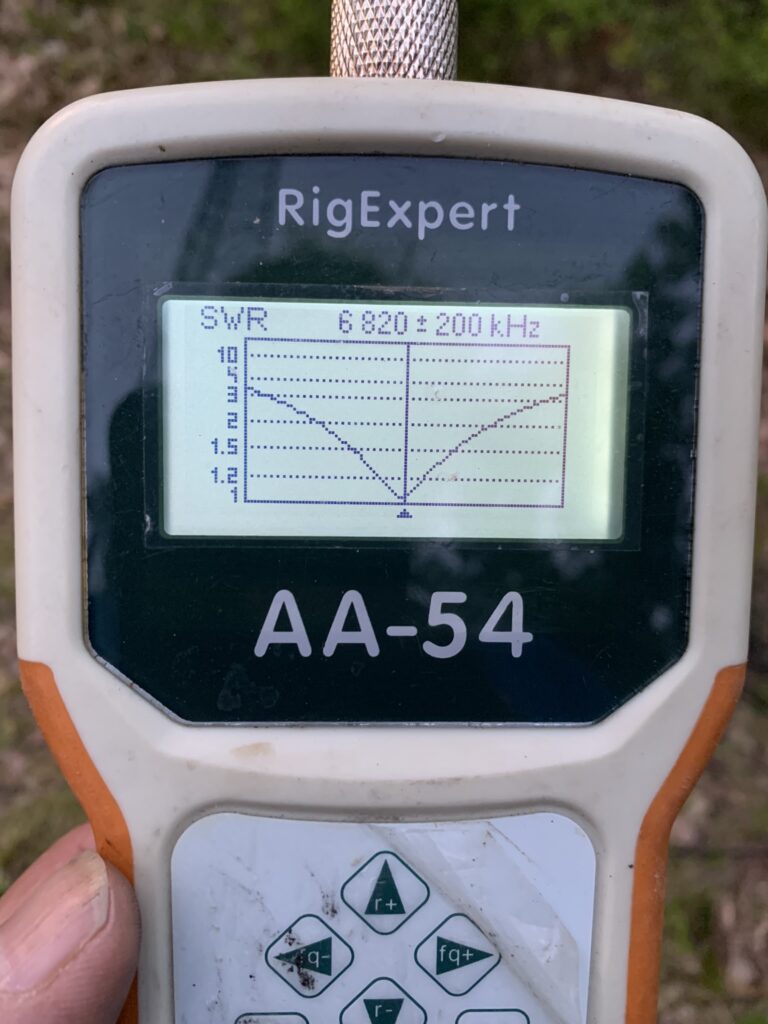
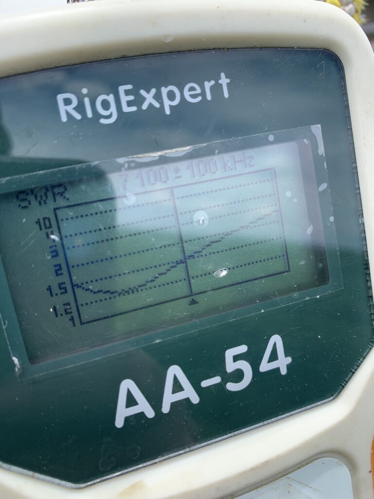
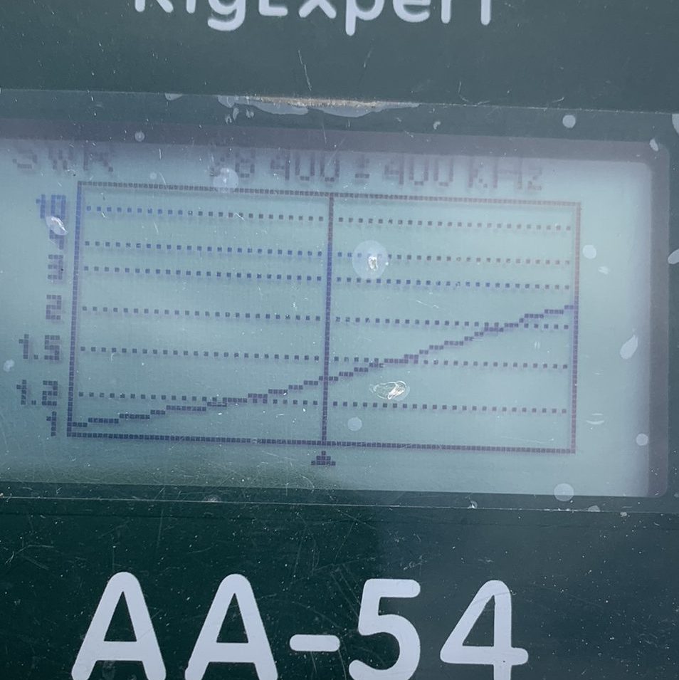
Grabbed the AA-54 to check the SWR and was happy to see it look very similar to how the first antenna did when it was at the same mounting height.
SWR curve for the antenna at 5′
August 14, 2022
Mark KA1YQC and John KF1KI arrived on a beautiful Sunday morning to help with the antenna raising. The first order of business was to remove the 4-ele 10 that had been installed at the 70′ level. After several evenings of studying plots using the HFTA Software that comes with the ARRL Antenna Book, I realized that the 40 needed to be at that height. The two 10-meter beams were better off lower on the tower.
You hate to go backwards on a project, but it seemed easier to take this antenna down rather than try to work around it.
Removing the 4-el 10m (KA1YQC photo)
The next step was to raise the side mount that would hold the lower 40.
Rohn side mount ready to go up
Then it was time to raise the 40-2CD. We thought about using a tram, but it seemed like it might be more trouble to set up than it would save in time. Decided to corkscrew the antenna through the two sets of guys. This was complicated a bit by a close tree that snagged the elements a few times.
K5ZD twisting the 40-2CD around the guy wires and trees (KA1YQC photo)
John and Mark did a great job of lifting and lowering as needed. And watching for times when the antenna would snag something behind my back.
Happiness is finally getting the antenna onto the side mount. The reflector was clear of guy wires and trees, but the driven element was much closer to the guy wires than I had expected. The use of Phillystran for the guys will prevent any performance issues, but we don’t want the antenna rubbing the guy wires in the wind or under snow load. Might have to raise the antenna couple of feet to get more clearance. Something to keep an eye on.
K5ZD attaches the beam to the side mount (KA1YQC photo)
I was anxious to check the SWR now that the antenna was in position. It dipped exactly where I had hoped!
40-2CD SWR curve with the antenna in final position
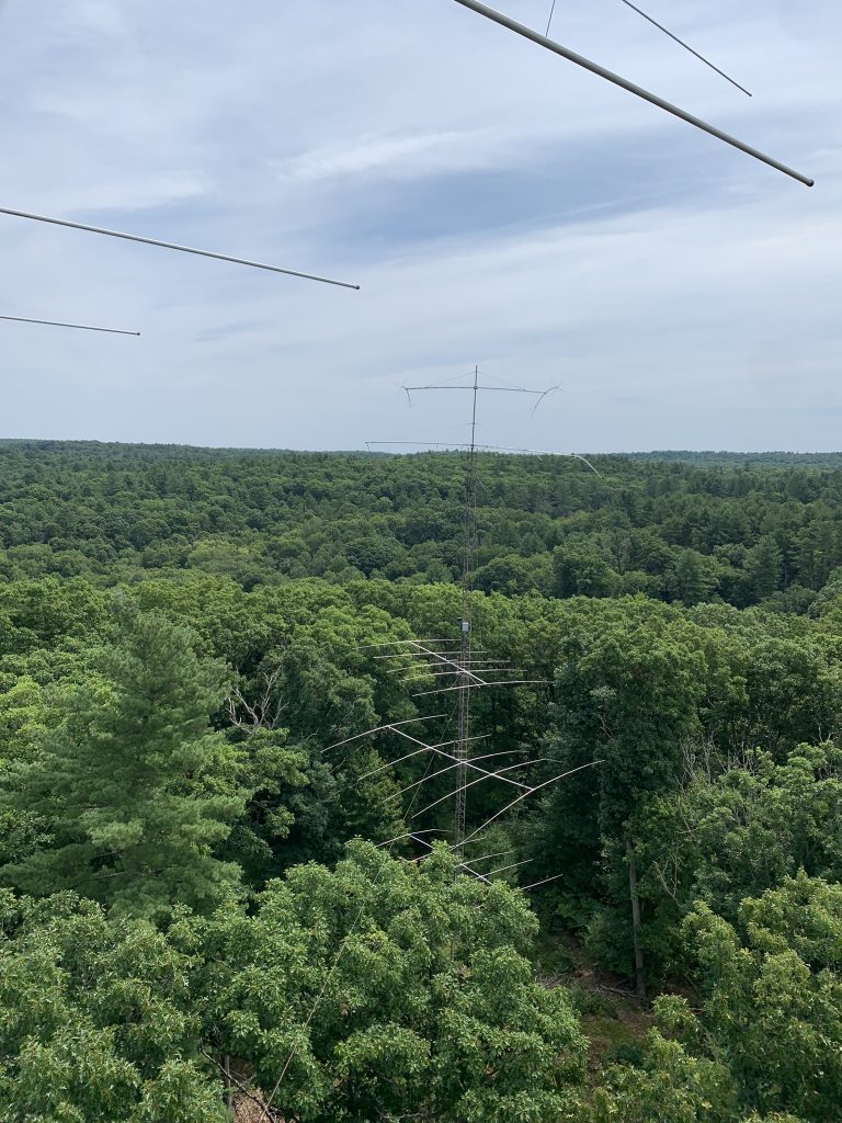
Nothing like coming down the tower and being able to take that first look back up to see the results.
First look up at the new 40m beam
It was only noon so we moved on to raising the two 4-element 10m beams into position. This was a piece of cake compared to the 40!
K5ZD moves the first 10m beam into position (KA1YQC photo)K5ZD bolts on the lower 10m beam (KA1YQC photo)
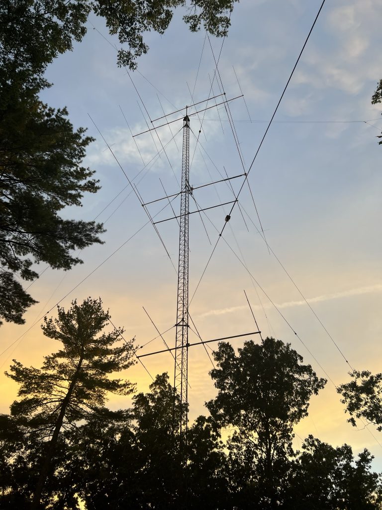
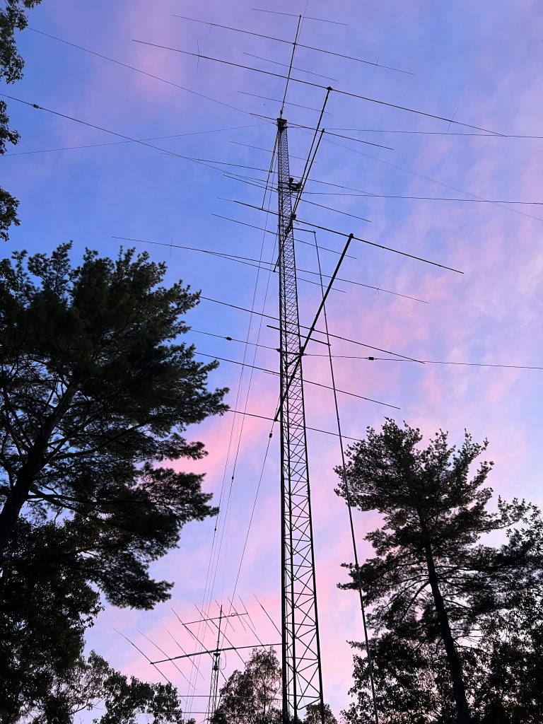
With all the antennas installed, we called it a day. I came back out to the tower later that evening to see a beautiful sunset that really highlighted the full antenna compliment.
Almost done. 2/2 on 40 @109’/69′, and 6/4/4 on 10m @100’/59’/29′
August 21-30
Worked on making the phasing lines for the 40m stack. Will write a separate blog post on that topic.
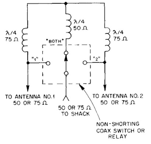
The stacking switching is fairly simple and uses just coax phasing lines.
Switching uses an RCS-8V 5-position remote coax switch that I purchased used from W1DXH. The RCS-8V can be easily modified to have any of the switch positions be shorted or open when not selected. Will use some existing rotator cables to get the needed 6 conductors from the box back to the shack.
September 2
Mark KA1YQC came over to help me get the cables and relay box installed for the 40m stack. Not a hard job, but nice to have someone on the ground to send the cables up as needed.
Replaced the temporary coax from the top 40 with a piece to get to the switch box.
Installed the switch box.
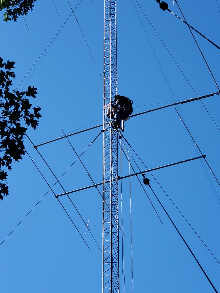
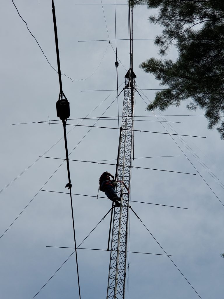
K5ZD installing switching and phasing lines (KA1YQC photo)
Installed the phasing lines. For now, they are just coiled up and tied off. Wanted to make sure things were working before tying things off.
I wanted to have equal lengths of feedline for each antenna. And for those lengths to be a multiple of a 1/4-wave. That means the low antenna has about 50′ of extra coax, but it worked out great for getting down from the top antenna.
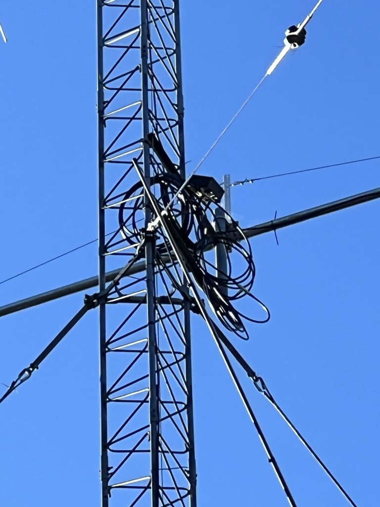
Temporary mounting of the 40m stack switch and phasing lines
We wired the control line back to the shack and were prepared to see success. The top position worked. The lower position worked. But not both. Argh. Checked the control voltages and they were correct going up the tower.
Climbed the tower to inspect things. Discovered the t-connector had failed. Argh. It is the one that has 3 female UHF connectors that ties the 3 phasing lines together. A new t-connector is now on order. (I should have known better than to use a cheap one I found in my junk box.)
The good news is that listening to Europeans in the early evening shows the low 40m being the best antenna at times. Will be interesting to see if/how this changes as we get into the contest season and operate the whole opening from our sunset to European sunrise.
Checked the SWR on the two lower 10m beams. The middle one looks ok. The bottom one is resonant way below the band. Could be interaction with the metal guy wires that are within inches of the elements. Will do more work with HFTA to see if that antenna can be moved up or down the tower.
September 4, 2022
While waiting for Amazon to deliver, I went up the tower and refactored all the coaxes around the 40m switch box. With a few days of rain in the forecast, I wanted to get all of the connections secured.
Amazon arrived while I was on the tower, so with the sun just going over the horizon, I made one more trip up the tower to install the new t-connector.
Argh. Still a problem with the both-position on the switch. And to make things worse, the high antenna only wasn’t working either.
September 7-9, 2022
Multiple trips up the tower to try to diagnose the problem. I probably made 6-8 climbs to the 70′ level and was up there for several hours. Just couldn’t make sense of what I was seeing.
When checking the wiring, I discovered that a wire had pulled out of the splice junction at the base of the tower. That fixed the antenna 1 problem.
I got some good advice from W2SC and N2NT on things to try for the phasing lines. Eventually tracked the problem down to a missed solder connection on one of the PL-259 connectors! I usually solder the shield and then wait for the connector to cool before doing the center conductor. Somehow I missed doing this one.
Whoops. Forgot to solder the center pin!
When you test quarter wave coax lines, you look for an open on the analyzer. When I checked the cable from one end it looked fine. But, if I plugged the analyzer into the end with the missing solder, it showed there was no cable. I guess you have to test phasing lines from both ends…
Once I found and fixed that, I was happy to come down to the shack and hear all 3 positions of the stack were working. SWR was good from 7000 to 7250. All positions of the new stack are better than my original 40-2CD on another tower. (It must have a problem?) The stack position seemed to be slightly better most of the time. Spent some time on 40 SSB in the WAE contest and the stack seemed to be a winner compared to the top or bottom antenna alone. Thrilled to finally see success after all this effort.
September 10, 2022
Mark KA1YQC came over on a beautiful Saturday morning to help me work on the 10m stacking.
We moved the lower 10 from 29′ to 32′. This got it out of the guy wires and just above the first set.
K5ZD removes the 10-4CD so it can be moved above the guy point (KA1YQC photo)K5ZD bolts down the 10-4CD at 32′ just above the first set of guy wires (KA1YQC photo)
Then we installed the WX0B Stackmatch box at the 65′ level. Checked SWR on each antenna as I did so. The bottom 2 antennas are resonant below the band. Is this caused by having Rohn 45G going through the middle of the antenna? Something to investigate.
We connected the control cable and headed back to the shack to check out work. All 3 positions could hear band noise. We listened to PT5J work Europeans in WAE. May need to investigate the wiring or the box as it didn’t seem like the right antenna was being selected as I switched through all the options. But, SWR was good across the band on all 3.
The last task was to raise and reattach the 160m shunt feed. This took no time and we were pleasantly surprised to find that the antenna was resonant around 1800 Khz. I had been afraid that adding 10′ to the tower and the second 40 would change the electrical height of the system. Will wait for dark to see if the antenna works.
Really enjoying having Mark’s help to take advantage of the fantastic early Fall weather to get things done before it gets rainy, cold, and windy in October.
September 21, 2022
On what is sure to be the last perfect day of the summer, Mark KA1YQC came over to help debug the 10m stack. We quickly determined there was a broken wire somewhere in the 250′ of cable between the shack and the base of the tower. It was the line that switched the toroid in the Stackmatch out when feeding a single antenna. No wonder the SWR and antenna selection was so weird. We grabbed a spare wire from the control cable to the 40m switching and things started working better.
The SWR on the low antennas was below 28.o Mhz. They resonated higher when tested at the 6′ level, but the extra height, guy wires, or Rohn 45 going through the middle was having an impact. We shortened the driven element on both antennas so they were resonant around 28.2, which kept the SWR relatively low from CW through 28.5 Mhz. Luckily this just meant rotating the driven element so both ends of the element could be reached from the tower.
K5ZD spinning the 10m driven element to adjust the length (KA1YQC photo)
Testing from the shack indicated there was something wrong with the low antenna. It sounded quiet and the SWR was height. We know the SWR was good using the antenna analyzer at the feed point, so it has to be in the coax or the Stackmatch. No amount of wiggling or unscrewing seemed to make any difference. So more diagnostic work needs to be done.
We also tried to find the tap point for the 160 shunt feed. We thought we had it, and then realized we did not have a solid connection from the feed point shield to the tower. When we added that, the R value was around 18 ohms. The tap point needs to be raised, but with sunset approaching, we decided to save this for another day.
October 12, 2022
One more very nice weather day. Mark KA1YQC came over and we attacked the 160m shunt feed. After some experimenting, we determined the shunt wire could not go through the 40. We attached it just below the 40 and were able to get it about 5′ out from the tower to get to 42 ohms. SWR is < 2:1 from 1800 to 1880 with a perfect dip at 1830.
K5ZD attaching the shunt feed (KA1YQC photo)
The First 160m QSO with the shunt-fed tower was with TO2DL in Guadeloupe (FG). At least now I know it can be heard.
Project Complete!
The project is officially done. All new antennas have been installed and the others restored to their previous configuration.
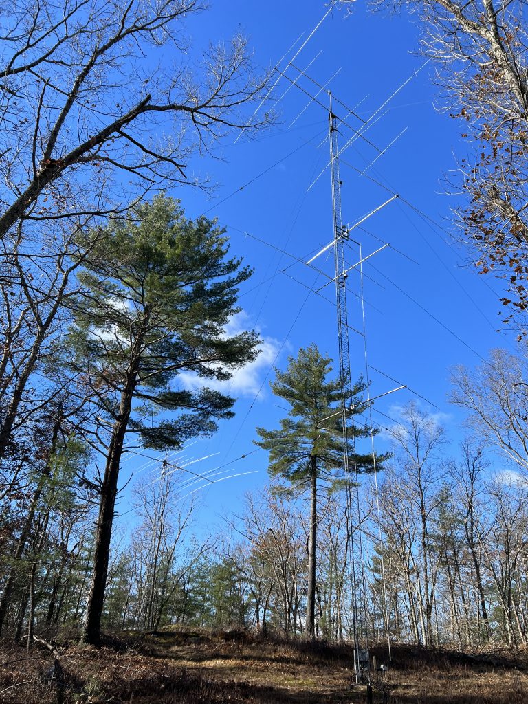
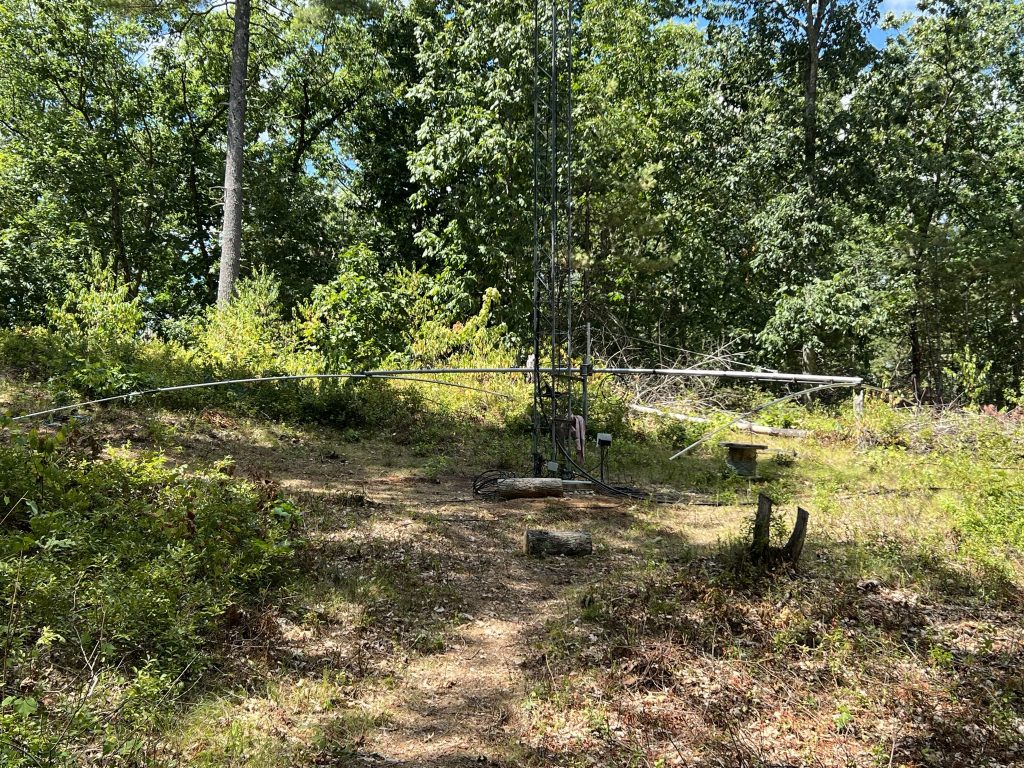
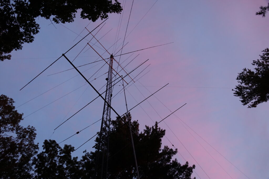
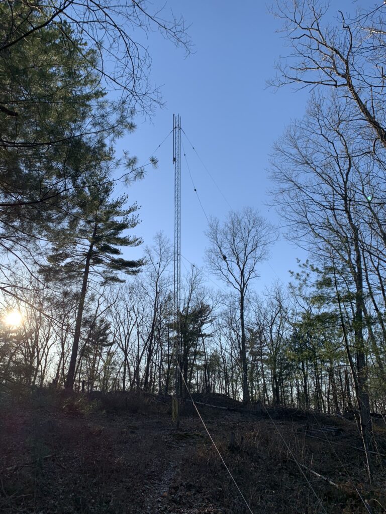
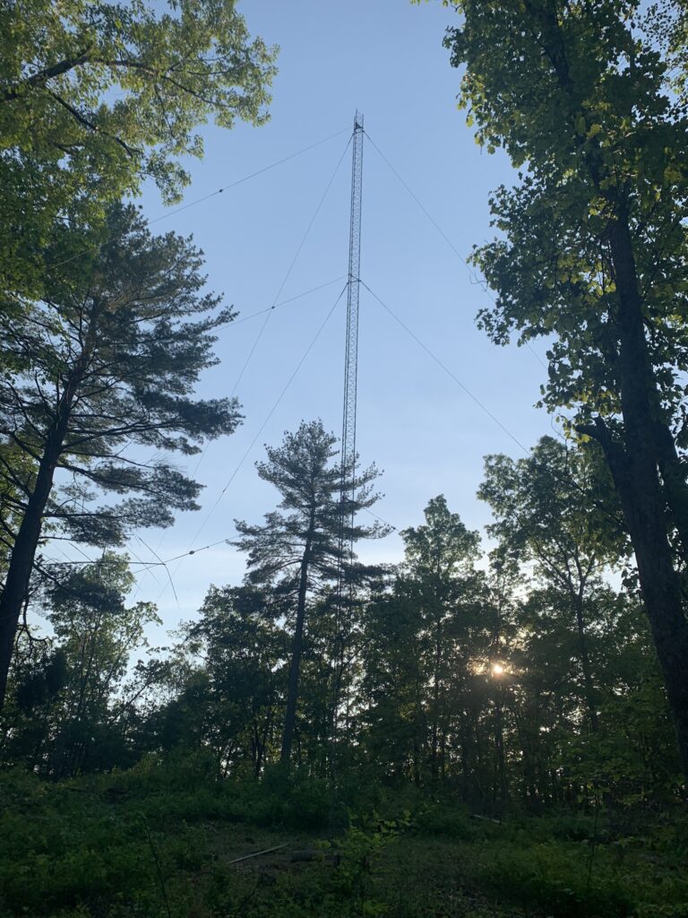
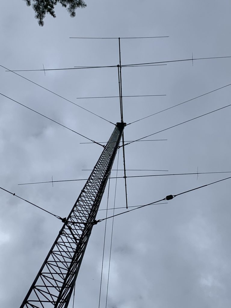
View of the finished antenna system.
Early results show the 40m stack is much better than my previous 40-2CD on the other tower. The 10m stack also seems to be working well. Finding the broken wire may have been all it needed.
Now the fun part – to get on the air and see how it all plays in the contests.
Thank you all for following the journey to this point. It has been a lot of work, but the kind that I really enjoy. Nothing has more hope than a new antenna system!
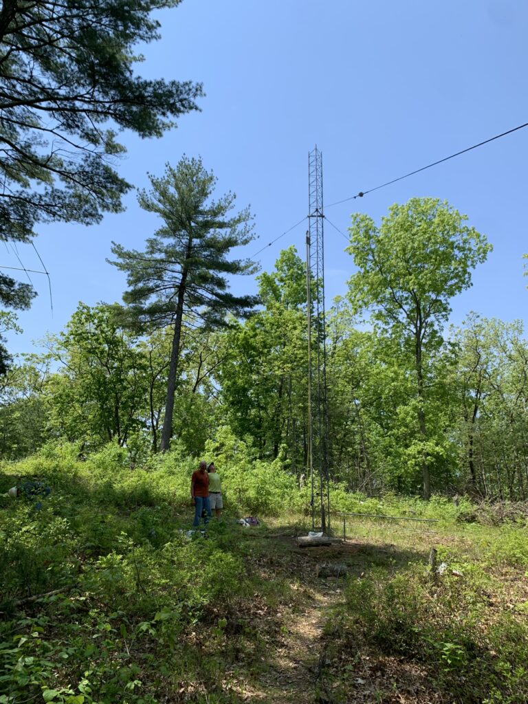
I want to put up another 40m beam. Not comfortable doing it on the Rohn 25G tower that I have.
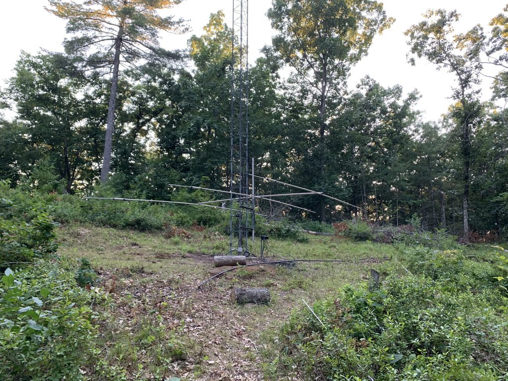
Tower 2, September 2018
September 2021
I had the opportunity to obtain 100′ of Rohn 45G from John K1AE. He lives about an hour from me. Making multiple trips and with a lot of help from YCCC club members, I was able to get the tower down over a 4-week span. I also purchased a Cushcraft 40-2CD that he had on the ground. I rented a U-Haul van to transport everything (tower, guy wires, beam) home.
New tower and accessories
October 2021
Took advantage of some nice Fall weather to touch up some rubbed and rusted spots on the tower so it was ready to go.
December 2021
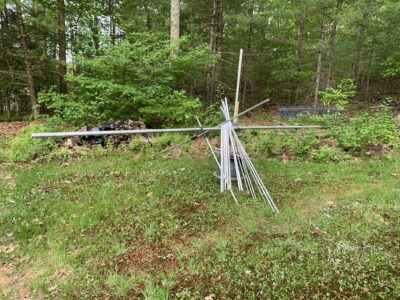
A tree falls over and lands on one end of the stack of 40-2CD aluminum. Argh. The only “safe” place for antennas is in the air!
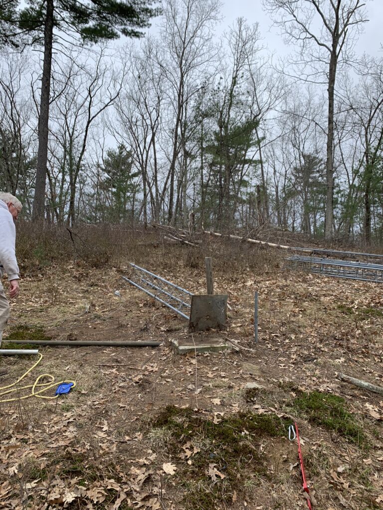
April 15, 2022
With the 3-day Easter holiday, I solicited help on the YCCC email list. Received a lot of generous responses and offers to help.
Martin AA1ON, Mark KA1YQC, and John NN1SS came down and we got started. We made much more progress than I expected – removing all antennas and getting down to the 60’ level.
In order, we removed:
80m dipole (freeing it up from the tree that had captured the feedline)
80m 4-square that was hanging from ropes strung out from the tower
40m sloper
160m shunt feed
Two 4-ele Cushcraft 10m beams that were side-mounted
30m dipole
6-ele 10m beam
Rotator
We corkscrewed the beams down the tower. 10 meter beams are so easy to manipulate…
Weather was sunny and nice, except for the occasional gusts over 25mph. Nothing like being 80’ up with the top set of guys removed and the wind deciding to blow harder.
One lesson learned. When a tower is a bit floppy, it is hard to get the sections to wiggle apart. NN1SS brought a Tower Jack and that saved the day. Sections that were more stable close to a guy wire wiggled right apart.
After everyone left, I took advantage of the nice weather to prepare the guys at 60′ for removal and installed the temporary guys at the 10′ level.
Stopping point
April 16, 2022
When I installed this tower in 1994 I had purchased a 1/4″ wall 12′ steel mast. Weighs just over 100 pounds. Never used it. Has been imprisoned in the tower ever since. I was a bit worried if the two of us would be able to handle it.
Martin arrived about 9am, and we had the last 60’ down in about 2 hours. We pulled the mast out of the tower when we got to the 20′ level. I won’t say it was easy, but the two of us managed it without incident.
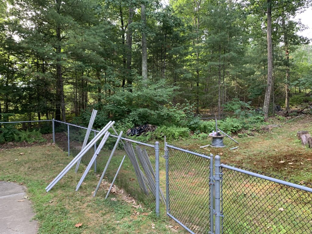
Tower is down
We were so far ahead of schedule that we had just finished when Ken WO1N arrived. I feel bad for letting him make the drive down.
I am now without antennas for 80, 30, and 10 meters. The crazy things we do to be just a little bit louder. 🙂
April 19, 2022
Made a run to visit Dave K1ZZ and pick up a 40-2CD antenna that he had been storing for Mark K1RO. “Storing” for the past 25 years! The antenna was in great shape and, after some hardware replacement, will soon be at the top of the new tower.
April 21, 2022
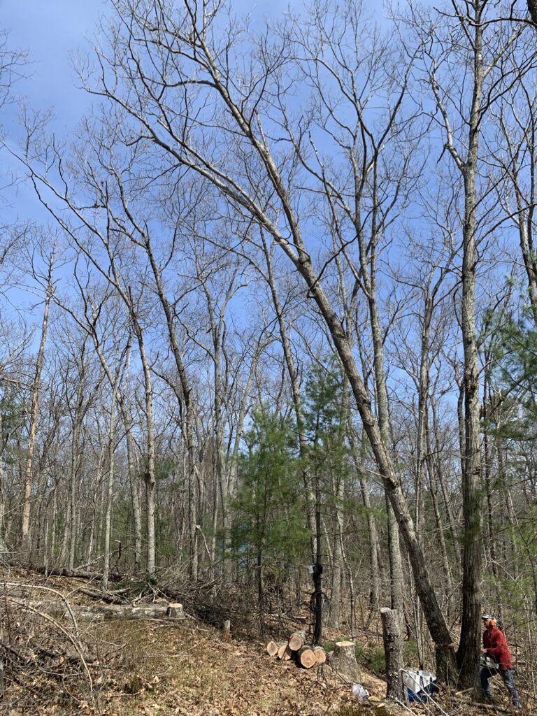
My friend Ron brought over his chainsaw and we took on the job of removing trees that had been growing into the guy wires. Always afraid of cutting down trees near a tower, so wanted to take advantage of this opportunity to clear things out a bit. Was perfect weather for getting the job done.
Ron cutting down one of the trees
These were big trees. Glad to get them down before the leaves came out.
April 23. 2022
Another great day to get some work done.
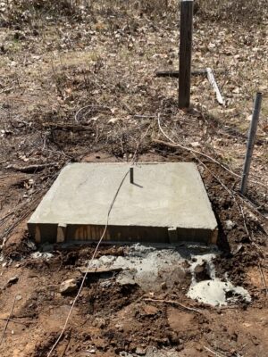
The original tower base was big enough to support Rohn 45, but I wanted to make the base a bit bigger to provide more support. Let me just say it is a long carry to get concrete from the driveway near the house to the tower base. A 350′ carry that is uphill all the way.
Mission accomplished.
Enhanced tower base
May 3, 2022
Spent some time taking the 40-2CD from K1RO apart and cleaning it up.
40-2CD cleaned up and ready for assembly
May 17, 2022
After two weekends lost due to some international business travel, it was time to get back to work. Started making up the Phillystran portions of the guy wires. Hard to believe DX Engineering gets 270′ of Phillystran on that small spool!
Phillystran and accessories
Will use Phillystran on the top two sets of guys. 60′ for the top set and 30′ for the middle set. Will go with steel wire broken up every 28′ for the bottom set. Why 28′? Because that is the length the guy wires from K1AE were already made.
May 20, 2022
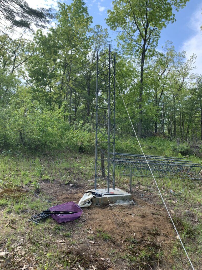
Mark KA1YQC came over and we hauled a few Rohn 45G sections up to the tower location. Then we put up the first section of the tower and installed the temporary guy wires at the 10′ level. Made everything tight and straight.
First section with temporary guys
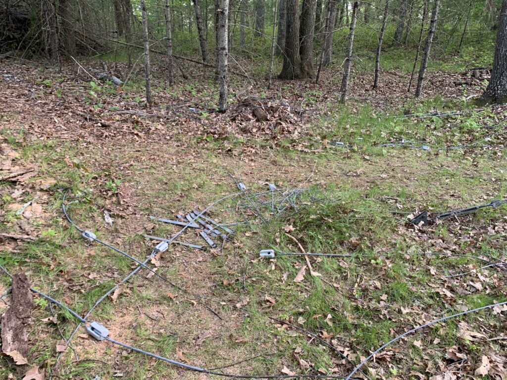
Spent the rest of the evening wrangling guy wires. Added the steel portion to the Phillystran. Replaced a few pieces of guy wire that showed signs of age.
Guy wire prep
Ready to start stacking tower for real tomorrow.
May 21, 2022
Joe KM1P, John KF1KI, and Spence AB1HO arrived to a cloudy and cool morning around 10 am. We quickly got 4 sections stacked up and the first set of guys attached by a little after noon. The clouds cleared and it became noticeably hotter. We finished tightening the first set of guys and removed the temporaries. By 1:30 it was hot and we had enough.
Up to the first guy wire attachment
One thing that slowed us down was guy wire lengths. The steel guys were broken up every 28 feet. When we pulled them out to the North and Southwest guy points, the insulator landed right at the turnbuckle. We had to undo the guy grip and change the length of the final segment from 28 to 22 feet. I probably should have done more math and anticipated this issue in advance…
May 22, 2022
It was a sunny warm day when Martin AA1ON, Mark KA1YQC, and Lars KE1J arrived around 9 am. The forecast was for temperatures into the 90s. I was a bit surprised everyone showed up!
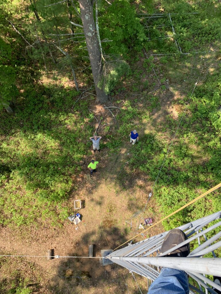
Tower view of the ground crew
Each new section was the same dance. Set up gin pole. Ground crew cleans out tower legs and puts in White Lithium grease. Pull up section. Get the sections to mate. Put in the small bolt for each leg (Rohn 45G has a large bolt and a small one for each leg). Then put in the large bolt for each. A drift pin is an essential tool for getting the holes to align. And a hammer to help the bolts power through the holes. Then tighten the bolts for each leg. Reposition the gin pole and repeat.
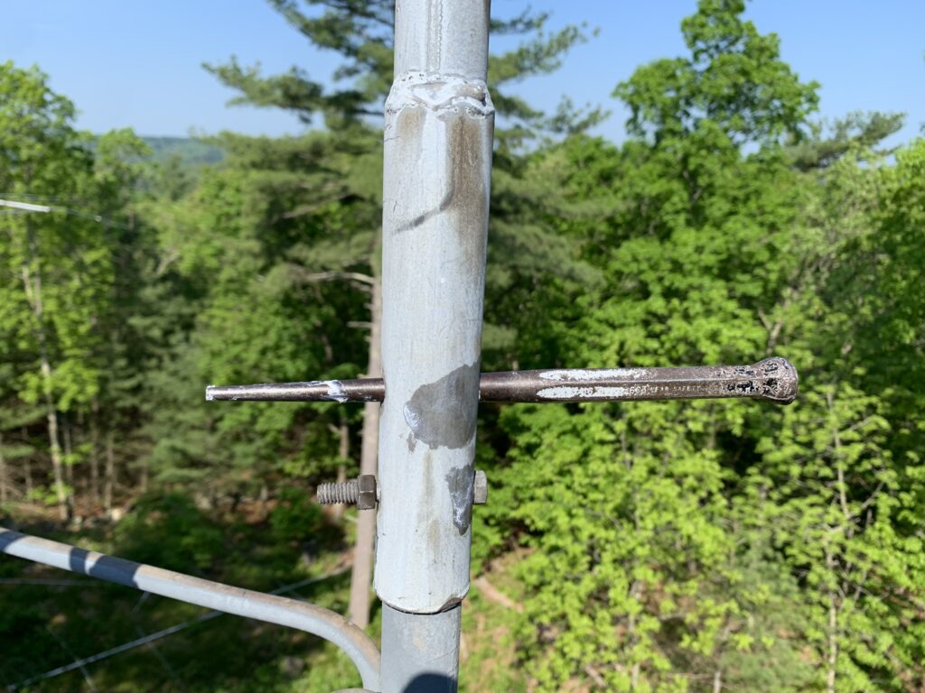
Drift pin for aligning tower bolt holes
We added 3 more sections, reaching the 70′ level. The second guy bracket was at 65′. The second set of guys had 30′ of Phillystran and then steel broken up with insulators down to the anchor. There were two guy wires where an insulator happened to be in the wrong place and required modification. We methodically made our way around the 3 guy points tightening turnbuckles while confirming the tower was still straight. The Loos tension gauge confirmed the guys were at the proper tension.
We took a short break as it was starting to get very warm.
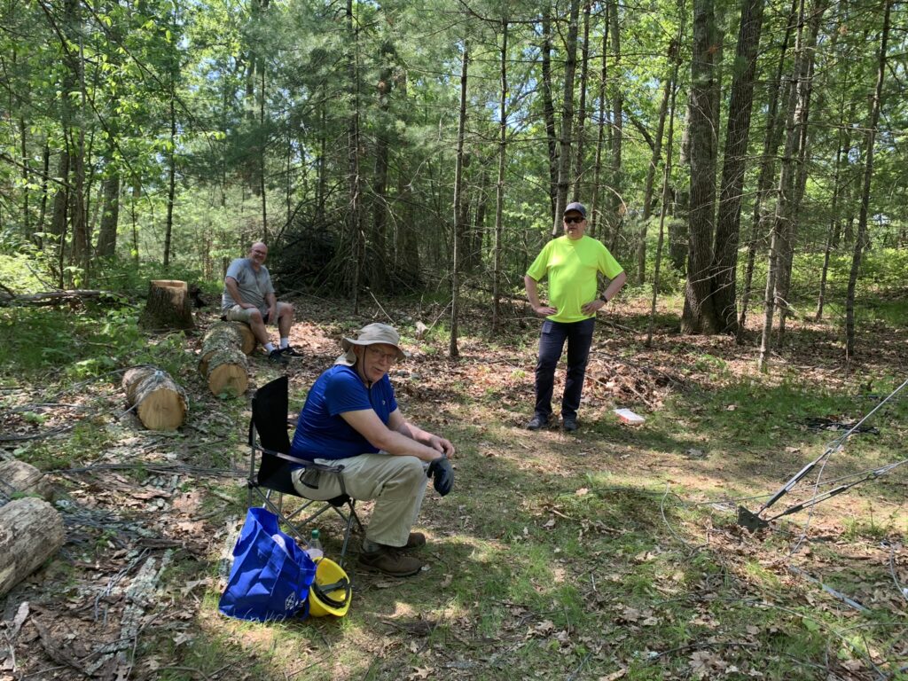
Mark KA1YQC, Martin AA1ON, and Lars KE1J (l-r)
Back up the tower to do the next 3 sections. We had decided to put the rotator plate and the guy bracket on the top section so I wouldn’t have to assemble them on the tower. Great idea, but the extra weight, and the 90′ pull, almost put the ground crew into the red zone. Of course, when the section got up there, it didn’t want to mate to the previous section. This required another heave to pull it off so I could spin it and try again. Oh, did I mention the wind came up while this happening?! I tried not to notice the subtle rocking that was taking place without the top set of guys in place yet… Nothing better than to get the legs aligned and then hear that satisfying thump when the section drops down to its proper place.
K5ZD digging through the tool bag looking for bolts (KA1YQC photo)
The ground crew did a great job. The breeze I was feeling on top of the tower was not so much down at ground level. The guys were pretty spent when we decided to stop.
Stopping point for the day. 100 feet
An empty tower is like a blank canvas. Ready for something great to be created. It was a very good day of progress. Tower only needs to have the top plate installed to be complete.
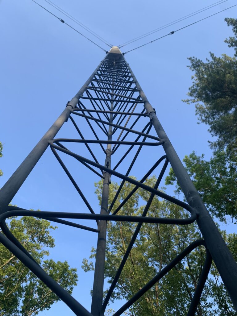
Looking up the tower
June 1, 2022
Finally back to working on the 40-2CD. The main work was to replace the aluminum truss Cushcraft provides with some stainless steel cable and hardware.
Assembly zone
June 6, 2022
Guy wire day. Focused on keeping the tower straight while also getting each guy wire to the proper tension as measured with the Loos Tension Gauge. Had one guy wire that needed to be adjusted as the turnbuckle had run out of room.
June 7-9, 2022
Rebuilding the 40-2CD. Carefully measured out each piece. Added reinforcement tubing inside the elements as possible. A dab of SS Jet 30 at each joint for long term connectivity. Also a stainless steel sheet metal screw to keep the pieces from coming undone.
I could not get the driven element pieces off of the center insulator. The only way to get the reinforcement piece in was to measure, mark it, then drive the piece of aluminum down the inside of each element. Had to be careful not to push it in too far as there was not going to be a way to get it back out. Added additional reinforcement to the first few element joints. The element is much less floppy than before the modification. It’s not the full W6QHS treatment, but hopefully, it helps with long-term survivability.
Two elements ready to go
June 10, 2022
Hauled the boom and elements up to the tower. Assembled everything to make sure I had not missed anything. The 40 is ready.
40-2CD assembled
Jun 11, 2022
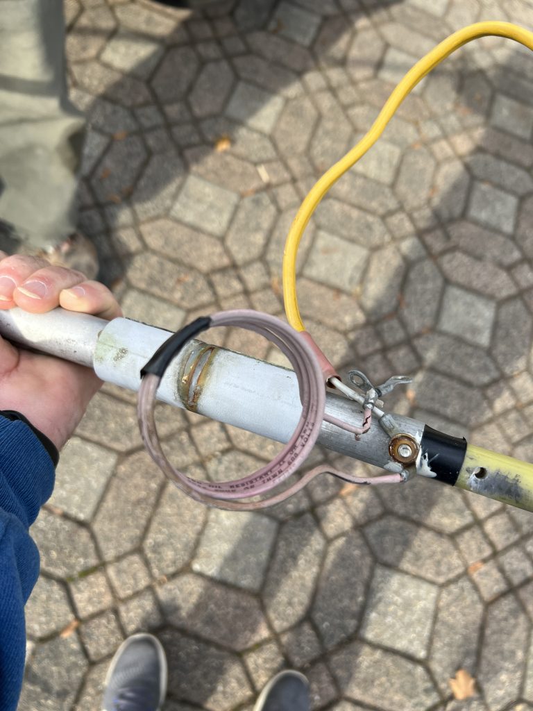
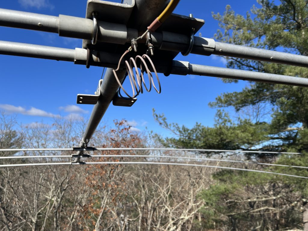
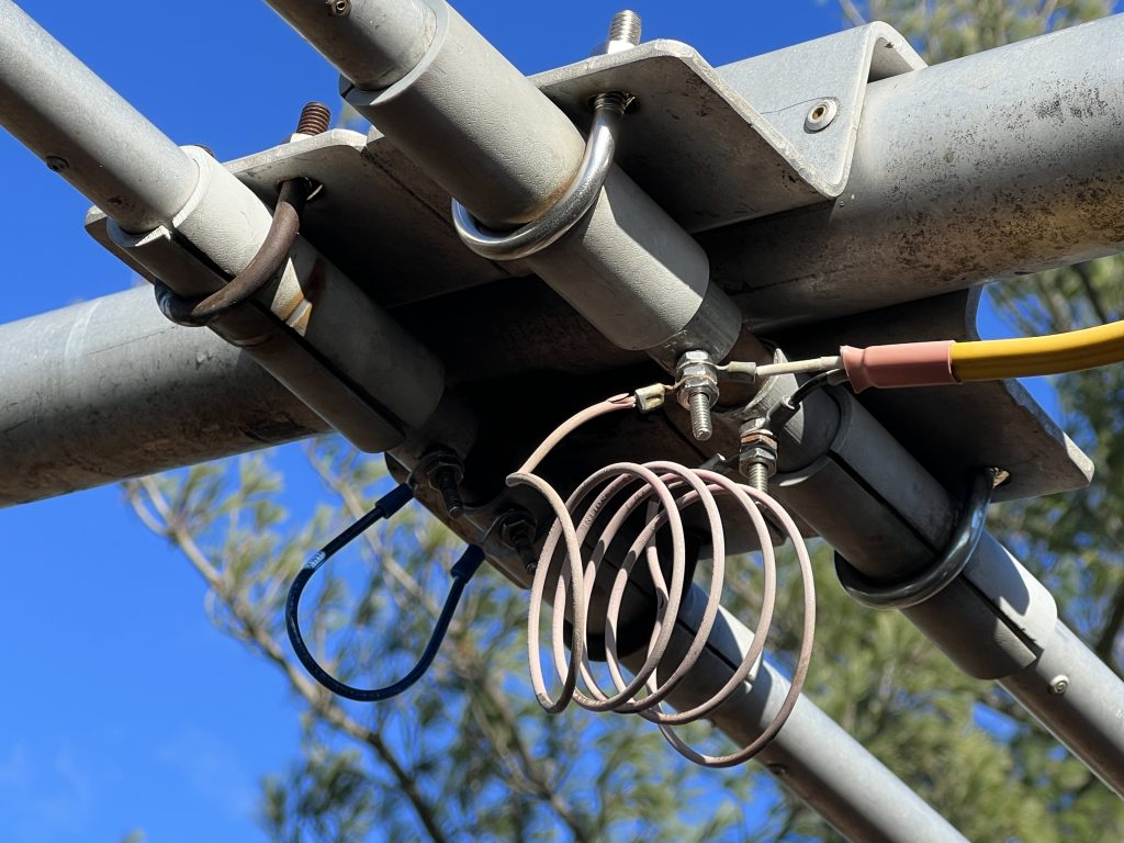
I was up early making final preparations for the 40m beam. Got the choke installed and enough feedline to get just above the top plate. I have learned the hard way not to end up with a coax joint in the middle of the rotator loop!
Trying something different with the choke. K3LR has reported some improvement in the choking impedance if the choke is separated from the boom. I put the choke inside PVC and used some rubber spacers to get it about an inch away. Maybe not quite enough separation, but good mechanically.
Choke mounting and feed point
SWR looks good, but hard to know with the antenna so close to the ground.
SWR with antenna at 5′
Martin AA1ON, Mark KA1YQC, and John KF1KI arrived around 10am. A bit of a delay as I made multiple trips back to the house for forgotten tools or parts. Started climbing around 10:40am.
First order of business was to install the top plate.
Tower is topped out
I had not fully accounted for the size of the rotator when I selected the original location of the rotator shelf. Took a few minutes to move it down one rung.
Then it was time for the mast. The ground crew hauled it up the tower without incident. They said it was much easier than the top section with guy bracket was! It was then that I discovered another engineering error on my part… the clamp holding the rope onto the mast hit the gin pole pulley with another 4″ of needed height still to go. Arrrggh! Luckily it was just close enough that I could lift the mast onto the top plate. After several tries and some colorful language, I was able to lever the mast up to the thrust bearing, then the bolt, then to the rotary part, and finally, with one huge grunt, lifted it over the edge and into the hole. Mission accomplished! I was determined not to make the guys have to lower the mast and lift it again. But, it was probably not the smartest approach. Next time, measure first!
Next up was to raise the 40-2CD. There is a pine tree that reaches in just enough that I wasn’t sure I would be able to easily corkscrew the antenna up the tower. Those capacitance hat rods on each element seem to always find any obstruction. I made the decision to assemble the beam on the tower. We pulled the driven element up first, then attached it to the tower with a strap and carabiner. Then repeated for the boom and reflector. I then attached the elements to each end of the boom.
K5ZD attaching the reflector element to the boom (KA1YQC photo)
Once the elements were attached, it was simply a matter of rotating the antenna to horizontal and dropping it onto the mast. The team on the ground was very impressed with the maneuver and how well it worked out.
K5ZD attaches the completed antenna to the mast (KA1YQC photo)
With the antenna secure, a call went out for the antenna analyzer to be sent up to see some early results. The SWR was very good, with the resonant frequency about 20 Khz lower than expected. Is it worth trying to adjust the driven element length?
SWR curve of the antenna at 100′
Of course, once we think everything is done and are ready to declare success, I noticed a small problem with the way I assembled the driven element. It is shifted about 1/2″ to one side, making the feed point attachment uncomfortably close to the u-bolt. Maybe not a big problem, but the u-bolt was a bit crooked. This will get fixed during a future session when we are ready to raise up the 10-meter Yagi.
June 15, 2022
I was joined by Mark KA1YQC to make the trip up to K1AE to pick up some 7/8″ hardline and the remaining pieces of another 40-2CD. We were met there by John NN1SS who helped load things into the U-Haul.
This is some serious hardline. I just hope there is enough to get a single piece that goes from the shack to the 10m beams that will be on the new tower (250+ feet). And that I can find some connectors!
Hardline and 40-2CD parts
June 18, 2022
I was joined today by Martin AA1ON, John NN1SS, Mark KA1YQC, and Spence AB1HO. It was a very cool day for mid June with a high temperature expected only in the mid-’60s. We had a stiff breeze from the NW once I cleared the top of the trees.
The first job was to fix the 40m driven element mounting. Popped the 40 off the top of the mast and was easily able to get to the feed point and slide it over about half an inch. Then popped it back on.
We brought up the Yaesu G-2800 rotator so I wouldn’t have to untie the rope until it was installed. We then raised the mast. This went very well, except for the few times I made the ground crew back up a bit because I didn’t tie the rope in the right place or forgot to tape the coax as the 40-2CD went up. Once the mast cleared the rotator plate, I was able to insert the rotator easily into the tower. I had a bit of an incident while putting the bolts in. I had left them in the plastic bag as they came from Yaesu. At one point I turned my hand so the plastic back dumped a few bits. They fluttered to the ground and left me one bolt short of having all I needed. Argh!
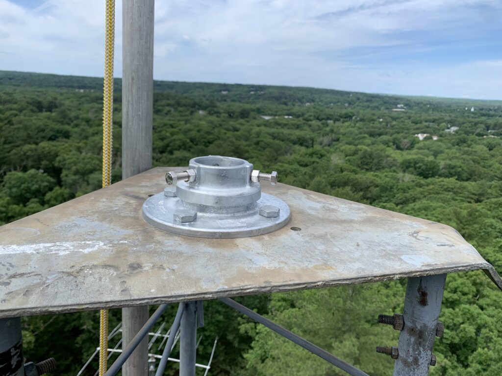
The DX Engineering thrust bearing to hold the mast at the top of the tower is a thing of beauty. But, the opening is slightly bigger than my 2″ steel mast. This put all of the weight on the 3 stainless steel bolts. Since the mast is so heavy, I didn’t want to take any chance it would slip. I added a safety u-bolt around the mast.
Safety u-bolt to help secure the mast at the thrust bearing
With the rotator secure, I climbed down for a break and to prep the 10m beam to go up. It was mostly ready, but I wanted to check the SWR before we got too far. Pulled the antenna up to about 20′ and the SWR minimum was way below the band. Not sure how that happened since the antenna was unchanged from how it came down 8 weeks earlier. We lowered the beam and started messing with the gamma match at the feed point. In the end, I think we shortened the driven element by 2″ or so on each side and moved the gamma shorting rod about a half inch. Looks much better on the AA-54, but not sure what we may have done to the performance…
The antenna easily corkscrewed up the tower and was bolted to the mast.
K5ZD finalizes installation of the 6-el 10m.The 10m beam is installed and ready for action.
Up came the antenna analyzer and it was great to see both antennas had the expected SWR.
SWR of 40-2CD at 109′SWR of 10m beam at 100′
It’s always nice to come off the tower and get to take that first look up to see the result.
Another milestone achieved!
The heavy work was done so we headed off to the local hamburger place to celebrate.
June 24, 2022
Dragged the rotator cable up the tower and connected the rotator. One continuous 350-foot piece of control cable to reach the shack. Was a bit disappointed to find the rotator would not turn. I had tested the full length of cable before I put it up, but maybe the wiring inside the connector at the rotator lost a wire… disappointed.
June 25, 2022
Field Day weekend. Perfect time to make progress on antennas. I spent some time trying to diagnose the rotator problem. Finally tracked it down to a connection at my cable panel where everything comes into the house. Argh. Very happy to see beams turning!
Ready to run some cables up the tower
Inspired, I climbed the tower to run coax cables for the 10m and 40m beams down to ground level. These connected up to the existing cables back to the shack. Field Day offered the perfect test for the new antennas. 40m worked great. Unfortunately, 10m was stone cold dead. Not even an FT8 signal! On Sunday the band was open and the 10m was confirmed to be working.
July 1, 2022
Mark KA1YQC came over to help get the 80m dipole reinstalled. This dipole goes between the two towers and required a bit of rope work to get the antenna tuned to the correct frequency and then worked around the trees. Nice to see a flat dipole at the 90′ level. This gets me back on all bands.
80m dipole going between the towers
Mark also brought over a Cushcraft A3WS that he doesn’t need. This is a 12/17 meter duobander. I have never had antennas for those bands so excited to get it in the air and chase some new DXCC band credits.
July 4, 2022
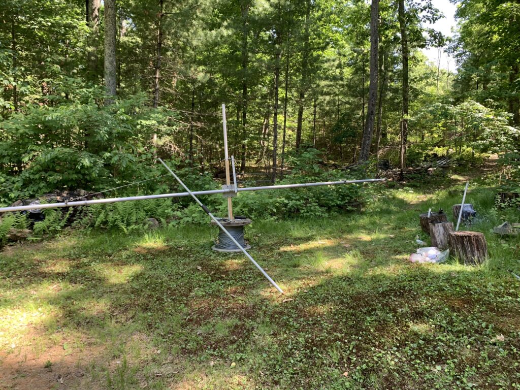
Built the A3WS and made some QSOs on it at the 5′ level to confirm it was ready for action.
Cushcraft A3WS awaiting final installation
July 16, 2022
Mark KA1YQC came over today. The first task was to install the A3WS at the 30′ level on Tower 3. Decided not to put it at the top of this tower due to 1) concern about its wind survivability, and 2) don’t want to risk any interaction with the 10 and the 40.
A3WS fixed NE at 30′
That decision freed us up to install the 80m 4 square rigging. This consists of running a rope out from the top of the tower in 4 directions and then using that to hold the top of the verticals. Can’t quite get enough height to make them vertical, but enough so they work.
80m vertical hanging from a catenary line
We had just enough energy to confirm the tuning on a Cushcraft 4-element 10-meter beam and raise it to the 70′ level.
K5ZD attaching the 4-ele 10m to the tower (KA1YQC photo)
In December 2019 I started experimenting with a new open source software for doing FT8/FT4 called DigiRite. It uses the WSJT decoder, but with a completely different user interface optimized for contesting. It is also well integrated with Writelog.
I spent the first few months of 2020 doing lots of operation and beta testing. The dev team was very responsive and the app kept improving. There was also the fun of learning the FT modes. FT is like having a contesting going 24/7. The QSOs are short and there is plenty of activity on all bands all the time. I had a separate Writelog log going just for my digi QSOs and could see the number of contacts and DXCC on each band.
I was always pushing to see how to make rate on the FT modes. The only SO2R operation that I did was during the WW Digi DX Contest in August where I did about 16 hours trying to run with two radios. The rest of the year was a single radio. I did use my amp most of the time (except 30m).
My operation was sporadic through the year. There would be periods where I operated a lot and then weeks with nothing. I became unemployed in September and started operating more and at different times during the day. The country counts started to build. I focused on trying to see how many bands I could achieve DXCC. It was fun checking the bands, seeing new “multipliers”, and trying to figure out how to get their attention. With the whole world in quarantine, the digi frequencies were crowded!
I had not worked the WARC bands much before this year so one objective was to try to get my DXCC on those bands. I used my Cushcraft 40m beam on 17M. I couldn’t find an antenna that would work very well on 12M. I finished WAS on 30 meters and only need ME and NJ to finish it on 17M.
I made over 1500 QSOs in December. In part because I could see the country counts getting close to 6BDXCC. 80 meters was the last band to make it on the evening of Dec 30 when I worked VU, UK8, and HP to get to 100 (while missing ZF and FG).
You may be interested in what is possible chasing DX on the digi modes for a year.
According the Writelog, I had 228.5 hours of digi operation. (Rate 31.5/hour)
One of my resolutions for 2021 is to help repopulate the CW bands. While FT8 is teeming with activity, and you can always see when the band is open and who is on, it is sad to tune across the CW segment and find no activity at all. FT is great for working DX, but it removes much of the human-to-human contact that helps build friendships and the shared experience that makes ham radio great.
Onward to a new year with less pandemic quarantine and more sunspots!
I put the Cushcraft 40-2CD 2-element 40 meter beam at the top of my tower in 1993. There are so many trees around the tower that we had to assemble the elements to the boom at the top of the tower. Actually it is at the top of the mast 10′ above the top of the tower! It lasted a long time before it started to be intermittent on receive.
John W2GD came up around 2016 and was able to climb the mast, get the beam in his hands, and rotate it so I could replace the feedline and feedpoint. It was less than a month later and the antenna started being intermittent on receive again. It mostly happened when the wind was blowing.
Just about the time John got the antenna reattached to the mast, I had noticed one of the loading coils looked mangled. It had a strange look like a bunch of birds had been pecking at the plastic. Since we had the antenna reinstalled, we didn’t pursue it.
The antenna kept getting worse and I would complain about it after every contest. In June 2020, Mark K1RX suggested that he had a fix that would solve the feedpoint problem and he was willing to help do the work. Mark does a lot of tower work for local hams and he is very good.
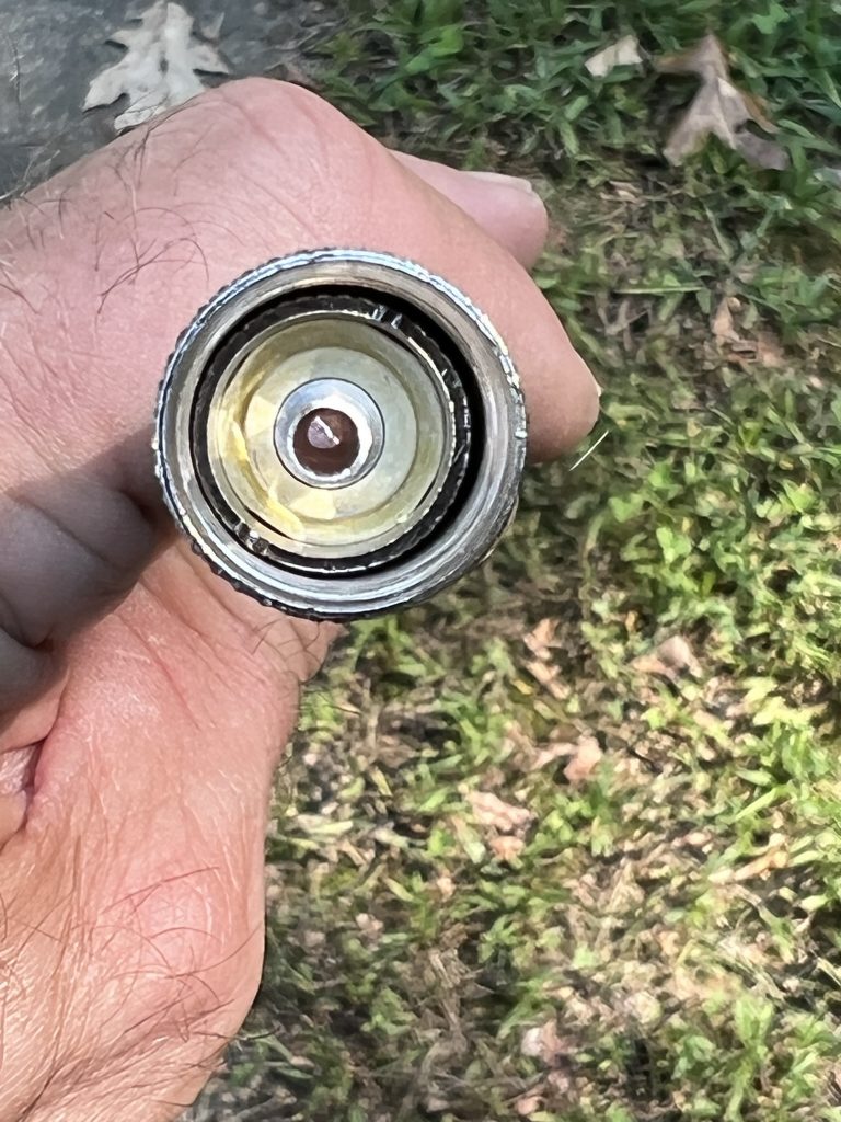
The feedpoint fix was to bypass the small through hole screws that Cushcraft used and replace it with some aluminum strap that went from the feedpoint, past the insulator, and out to the element. Mark came up with all the pieces from his junkbox. See photo below.
40-2CD Feedpoint “repair kit”
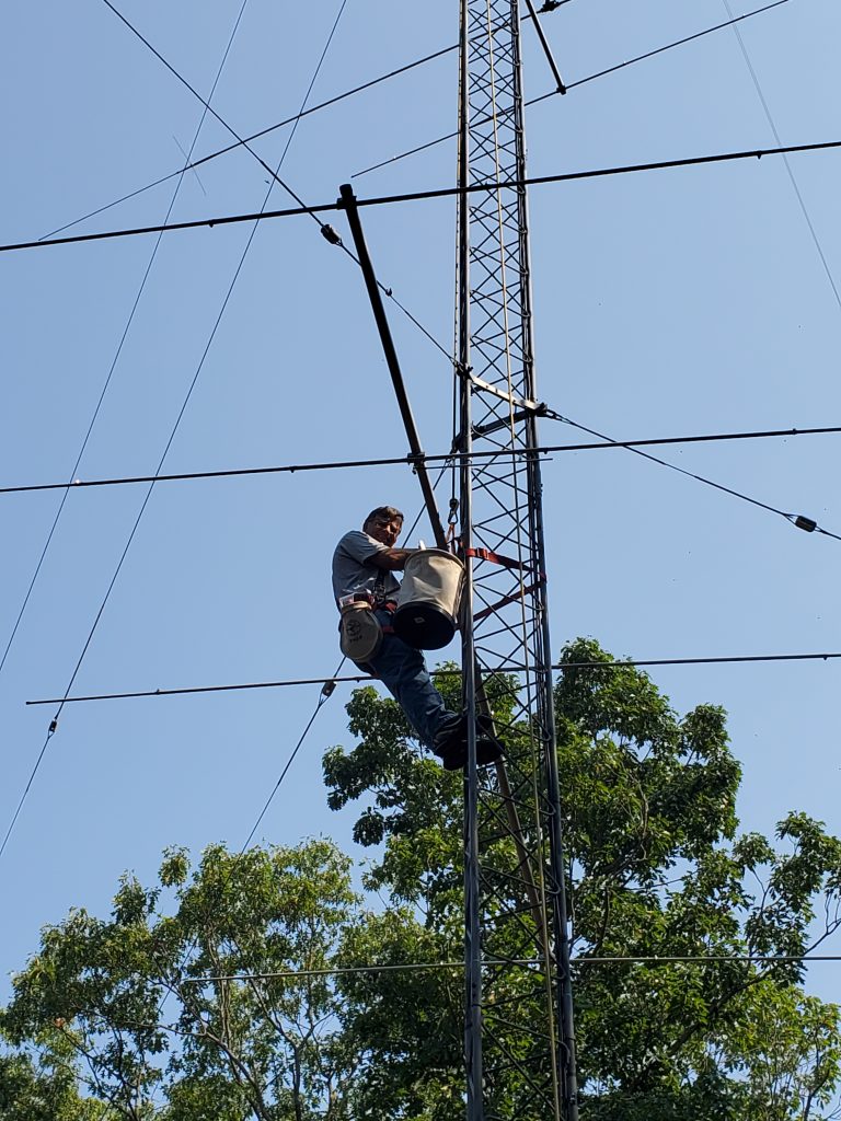
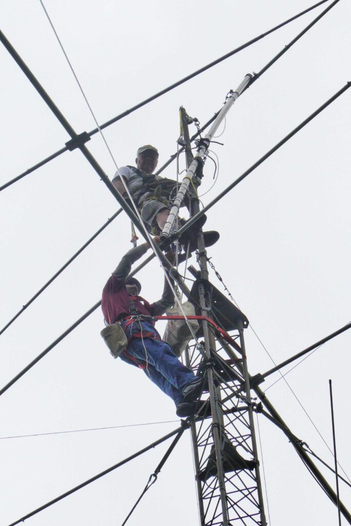
Mark climbed the mast and maneuvered the antenna so I could reach the feedpoint. I added the straps, reattached the coax, and then weatherproofed everything.
Fixing the 40m antenna feed point. (K1IR photo)
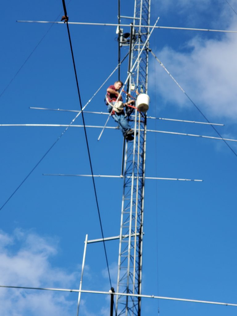
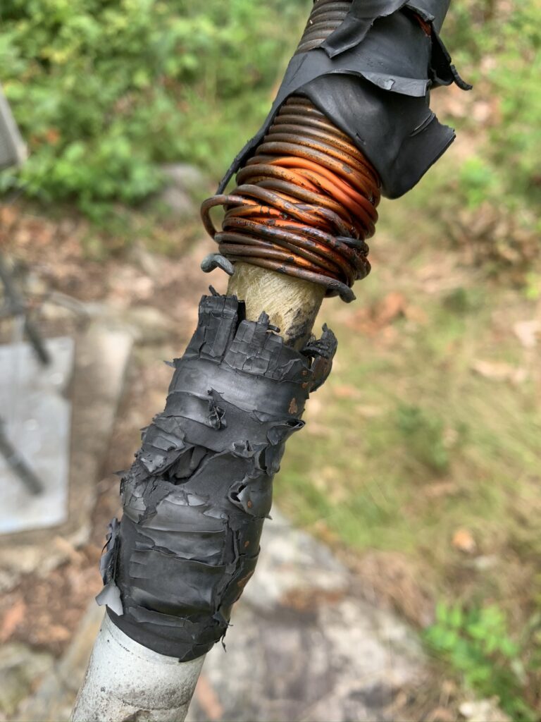
That mangled loading coil had also been bothering me for a few years. All attempts to get a photograph or better visual to diagnose were unhelpful. Since we had the antenna off the mast, Mark was able to get the coil to where I could reach it. Wow! Lighting damage. The coil had been vaporized on one end and the wire had unspooled. I had effectively been using a dipole in contests for 3+ years!
Lightning damage to 40-2CD loading coil.
I have collected a few 40-2CD elements over the years just in case something like this happened. We were able to find a good one in the junk pile and replace the fried one. I was excited to have that mystery solved.
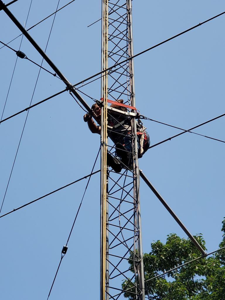
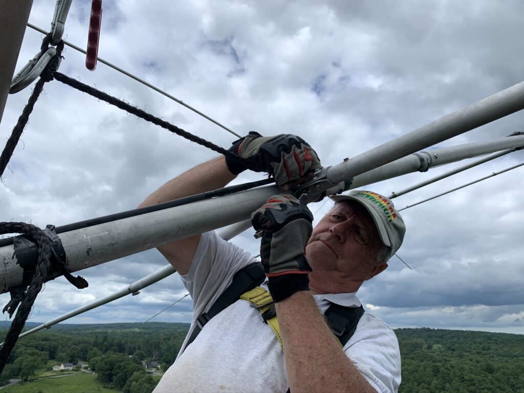
A recent wind storm had caused the truss wire on the Hygain 205-CA 5-element 20 meter beam to fail. Since we were up there, we took on the job to replace the truss on both sides with new stainless cable. A 205-CA is a big antenna and the truss wires go out near the end of the boom. Mark had to remove one of the elements to get the antenna to lean over far enough so I could reach it. It took all of Mark’s strength to wrangle the antenna.
Mark K1RX removing the element.
The end result has both good news and bad news. The 40 meter beam now feels and sounds like a beam again. I.e., it has front-to-back and I have had a bit more success on 40 in the past few contests. The SWR curve is back to looking like it did when I first put it up.
The bad news is that the antenna is still intermittent at times on receive. Signals will fall about 20-30db when the antenna is not working. Sometimes transmitting with 100W is not enough to clear it. But, so far, a quick blast with the amplifier on always brings the SWR back in line and the signals up.
I climbed the tower one evening with a long pole hoping I could bang on things and find where the intermittent might be. With the antenna analyzer connected, I could see the high SWR. Banging and prodding did no good. I could not quite reach the loading coils. Only when I violently pumped the antenna up and down would the SWR intermittently come down.
This 40-2CD has the W6NL mods so it has been extremely durable at resisting wind and weather. Given the lightning damage on the reflector trap, there is no telling where the failure point is on the driven element. As long as transmitting will clear it, I will live with it. But, sometime next summer it will be time to make another try at finding the problem or replacing the element.
Thanks to Jim K1IR for serving as ground crew during the climb.
(l-r) Randy K5ZD, Mark K1RX, Jim K1IR (K1IR photo)
For several years I tried using the sound card in my station PC to handle voice keying. No matter how much I messed with it, I could never make it sound great. The audio would be too hot or too quiet. I did a contest at P40L where the voice keying was done using the Elecraft K3 built-in DVR module. It sounded great so I added the DVR to both of my K3 radios.
WriteLog has the ability to send commands to the radio. The commands can be triggered from the keyboard. It is not difficult to do, but it is not obvious and I wanted to have a record if (when) I need to do it again.
The first step is to tell WriteLog what radio commands to send. You do this by editing the writelog.ini file and adding a section Elecraft_K3_commands.
The K3 has a bunch of commands to do things like clear the RIT, go split, etc. See the Elecraft K3 programmer manual for explanation.
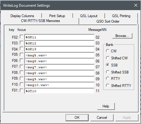
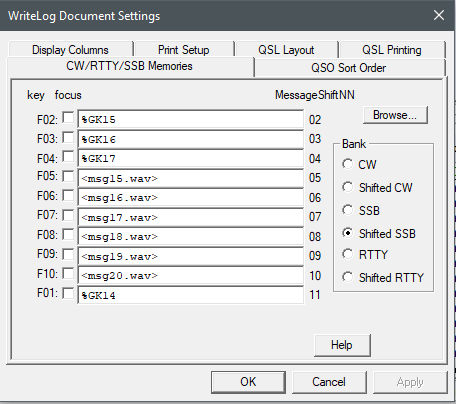
The next step is to connect the radio commands above to the messages. You replace the normal <msg#.wav> file with the link to the radio command. That uses %GK and the macro number. See below for how it looks in the SSB memory dialog.
If you want to program your DVR messages on the fly, you can add the Shifted SSB memories as well. Or you can just use the buttons on the front of K3 to do message programming since it is not something that you typically need to do often.
The memories are stored with the log so you will need to set them up for each new contest. Once you have it working for one phone contest, you can copy them in by using the Browse button on the memory setting dialog and select a .wl log file that is already set up.
That’s it, you’re done! Pressing the F1 function key will play macro 14, which is message M1 on my K3.
The best thing about this is that your audio through the DVR will always play with the same settings as the audio from your microphone.
Sending Commands with Keyboard Shortcuts
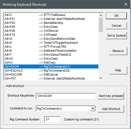
The example above is for using the internal K3 DVR to send voice messages. It is also possible to configure keyboard shortcuts to send other commands to the radio. For example, I set up a macro to command the rig to set VFO A = VFO B, then move VFO B up 1 Khz, then go into split mode.
As before, the first step is to add the K3 commands to the writelog.ini file. Here are some examples:
SWT13 is a switch-emulation command that has the same effect as tapping A>B .
FT1 enters split mode.
The number 5 in UPB4 is not a value in kHz, but an index into the table of step sizes (in this case 1 kHz). VFO displacement, n: 0=1 Hz; 1 or not used=10 Hz; 2=20 Hz; 3=50 Hz; 4=1 kHz; 5=2 kHz; 6=3 kHz; 7=5 kHz; 8=100 Hz; 9=200 Hz.
RT0 and XT0 turn off RIT and XIT.
The next step is to use the keyboard shortcuts dialog to define which key will trigger which macro. In the example below, I have set the Ctrl+DASH key combo to send macro 21 to the K3.