C31xr Installation Project (November 2023)
I have been using a Hygain TH7DXX as my south antenna ever since I built the station in 1993. It has served me well, but some years ago the SWR on 15m started being a problem. I could still work people, but having an SWR of more than 2:1 bothered me. No amount of changing things seemed to make it better.
In November 2023, Pete W1RM posted a message that he was looking to sell a C31xr that he had recently replaced with a JK tri-bander. I jumped on it.
Mark KW1X and I drove down to Pete’s place in CT to pick up the antenna on November 15. You can see Pete’s new antennas in the background.
Here is the complete kit as it arrived at my place.
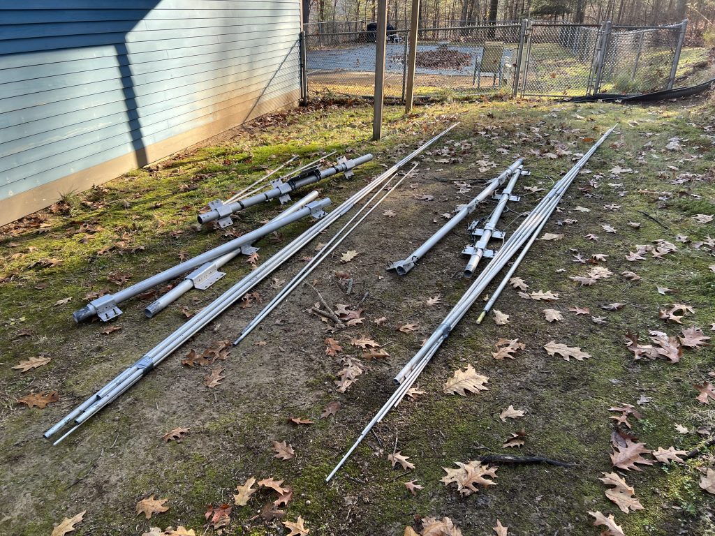
It was now 2 weeks before CQ WW CW and I was determined to get this antenna in the air before then. The first step was to haul all the pieces up the hill and start assembling.
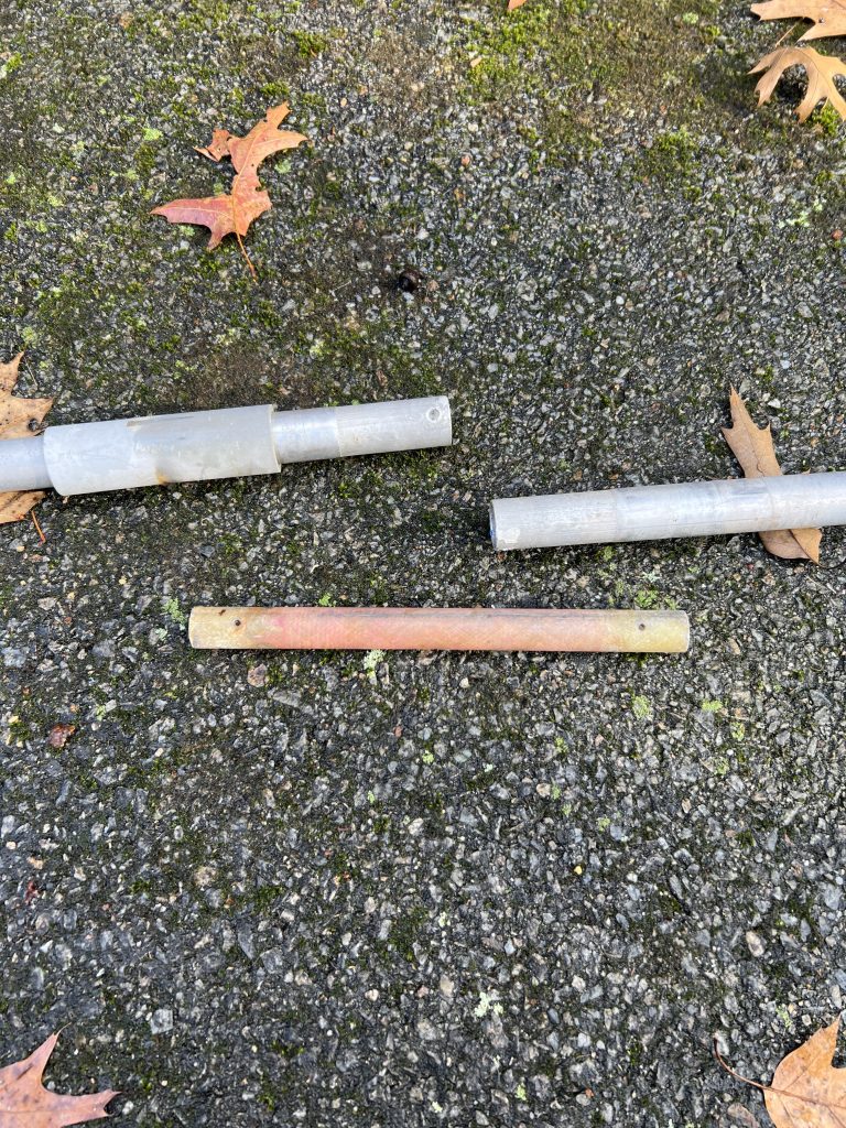
Some of the driven elements use a non-metallic spacer to isolate the element halves. As I put things together, I realized that I was missing one of them. I didn’t have much time so I tried to use a wooden dowel. It couldn’t handle the stress and quickly failed.
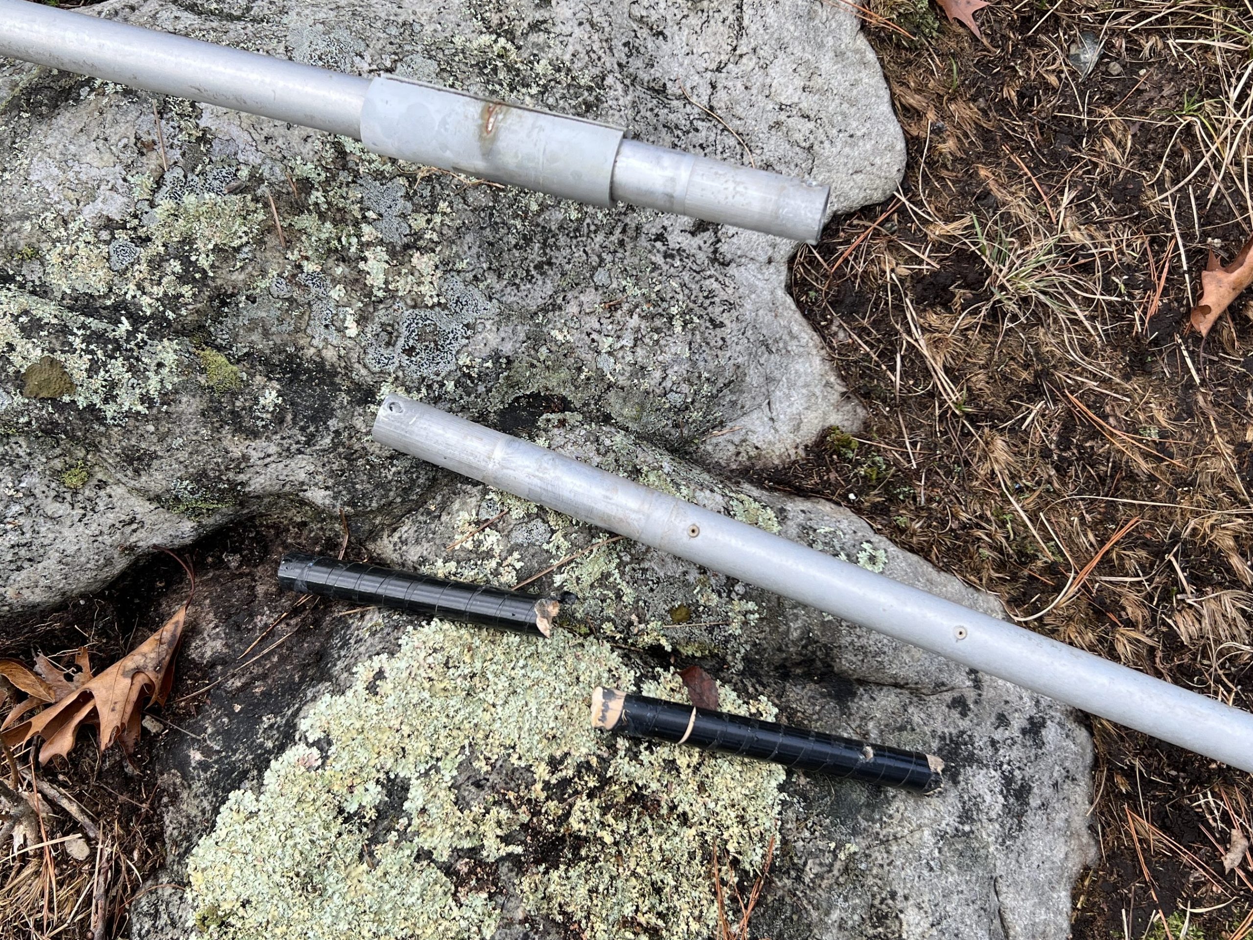
I had some extra loading coils left over from rebuilding the 40-2CD stack in 2022. Amazingly, one of the fiberglass rods that make up the coil was a perfect fit! It definitely had the required strength.
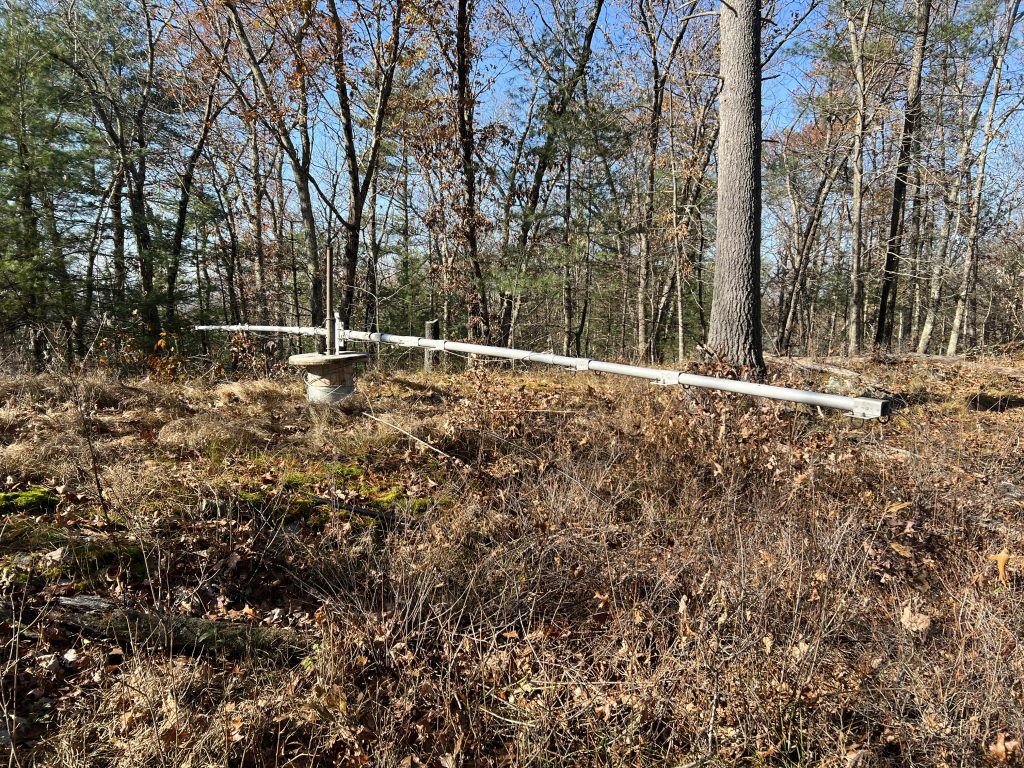
Antenna assembly went quickly once that disaster was averted.
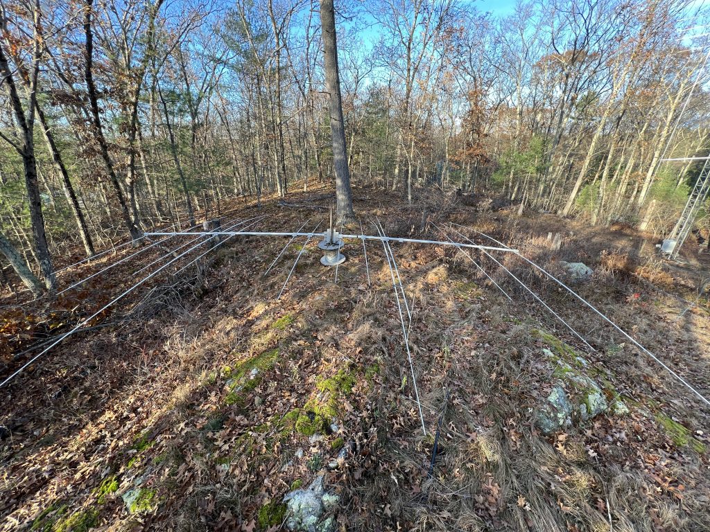
I did not truly appreciate how big this antenna was until I started to assemble it. Long boom, lots of elements (14!), and a total weight of over 85 pounds. I started to worry if it was going to bump into the trees that surrounded the tower (it did).
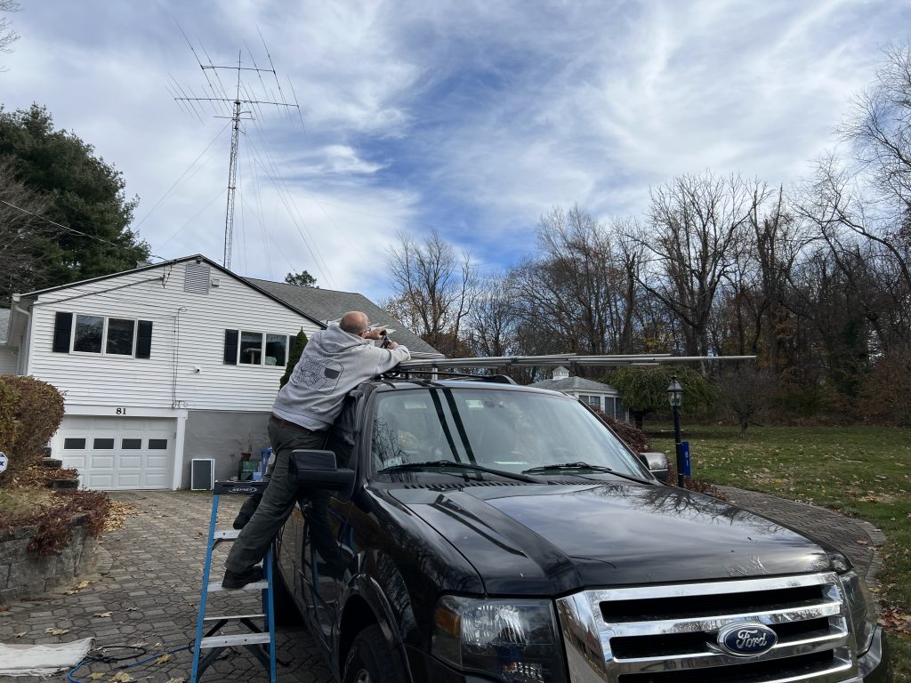
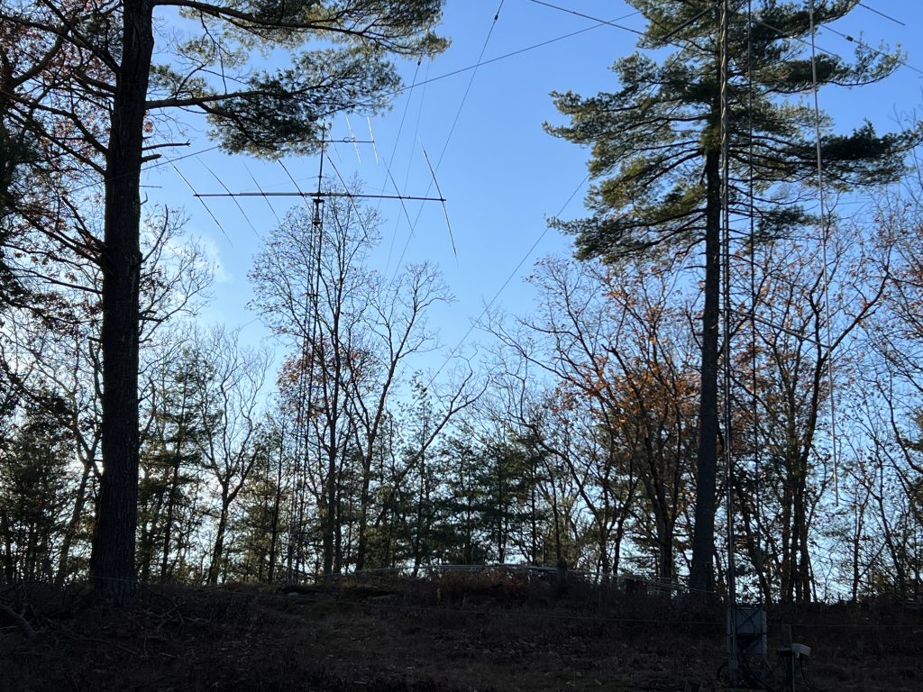
Mark KW1X and Martin AA1ON came over to help with removing the TH7 and putting up the C31. Here is the TH7 before removal.
With the help of gravity, we had no problem bringing the TH7 down the tower. This 40′ tower only has one set of guy wires at the 30′ level so it was not difficult to corkscrew the beams around the guy wires. The C31xr was heavy and it took all of Mark and Martin’s effort to pull it up.
I was happy when the U-bolts were in place and the antenna was attached to the mast.
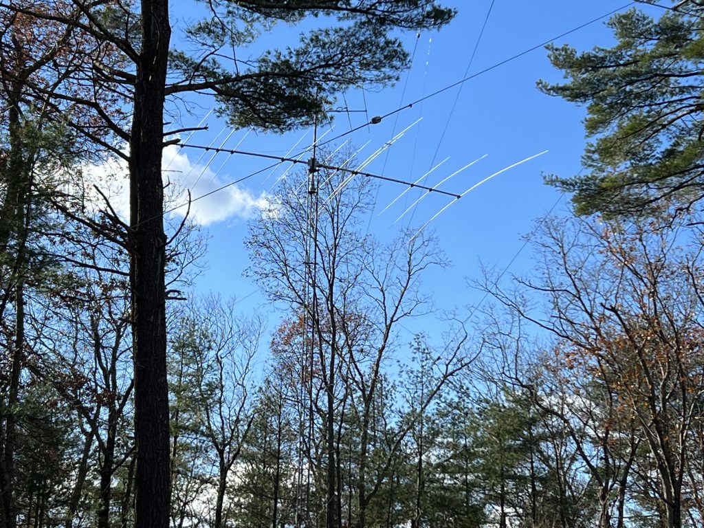
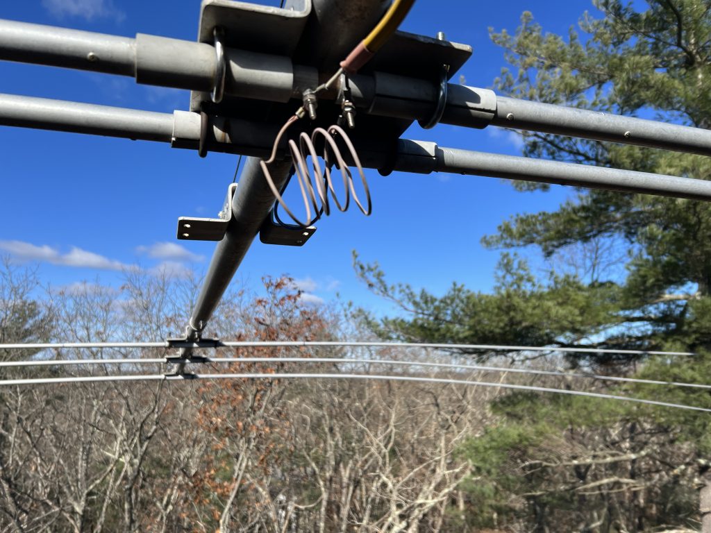
Here is the first look once I was back on the ground.
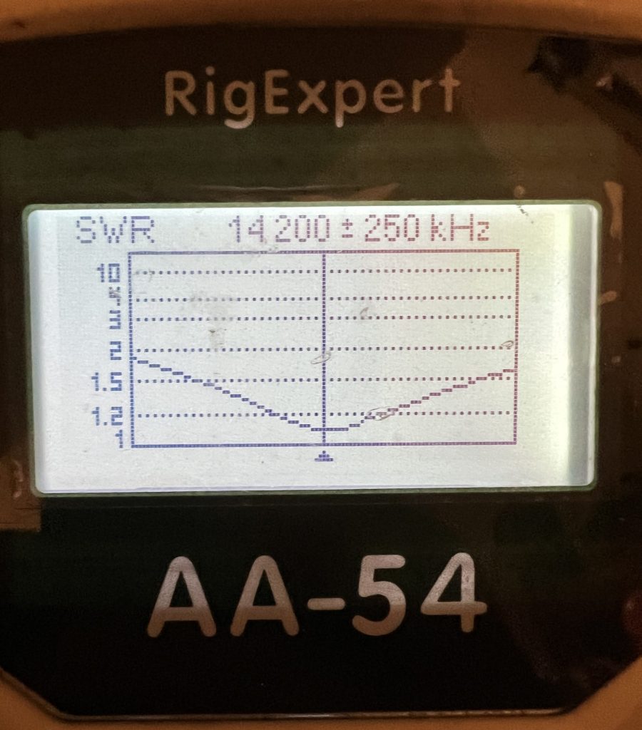
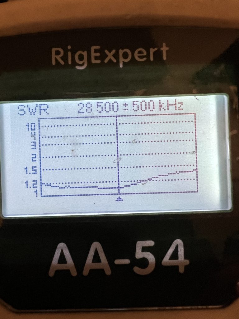
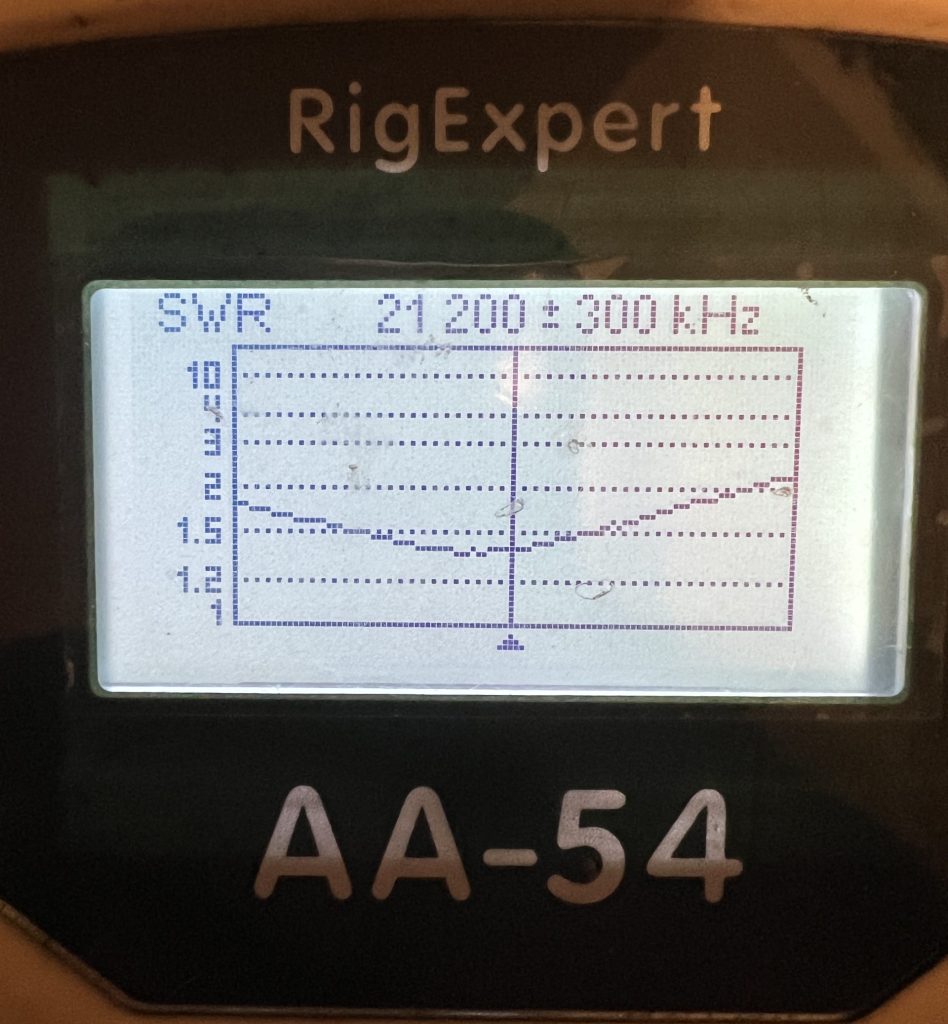
The next step was to check the SWR. Hmmm… not what I expected.
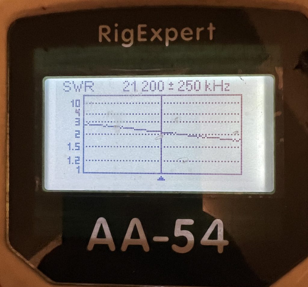
Discussion with W2GD and others who had a C31 indicated that having problems with 15m was not unusual. The first suggestion was to manipulate the loading coil.
I had put the antenna up with the coil the same as it was when at W1RM. The coil had the turns taped together.
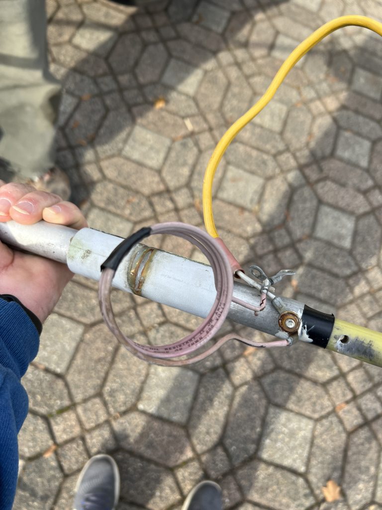
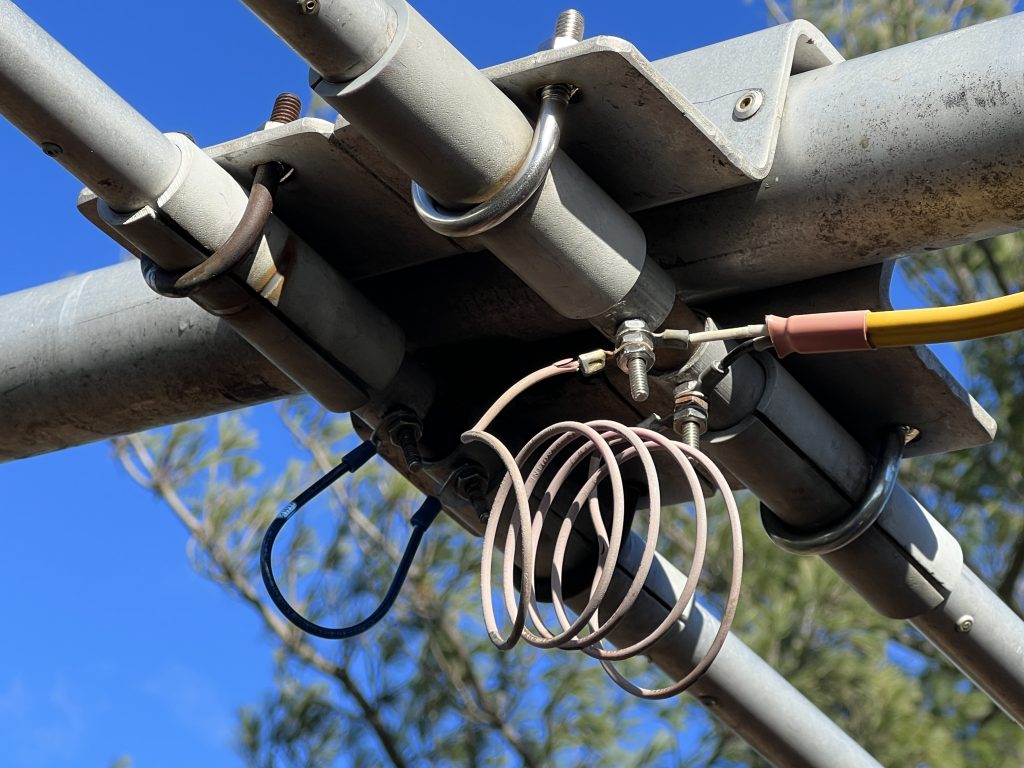
Luckily, I could just reach the coil from the tower. So on Thanksgiving morning (Thu before CQWW) I removed the tape and spread out the coil.
Another suggestion to move the SWR minimum on 15m down the band was to make the shorting jumper on the 15m element a bit longer. This was much more difficult to reach and involved holding the jumper in place while screwing on a small nut. I was scared I was going to drop the nut and never find it! I did manage to get it on and tightened up. You can see the jumper to the left of the coil.
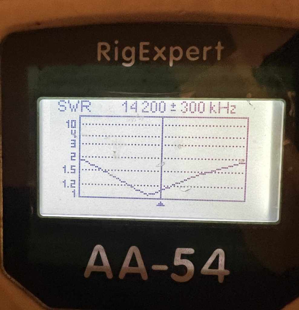
I was relieved and happy when I saw the results.
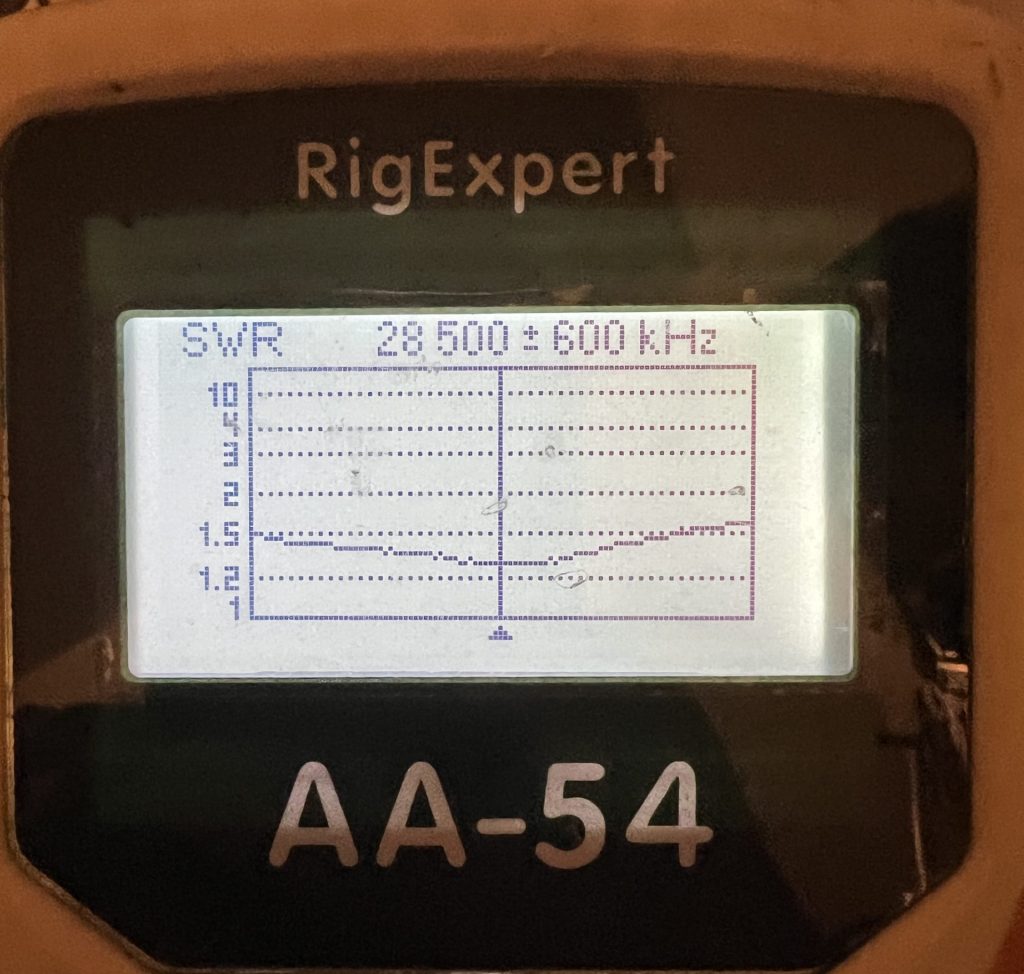
Mission accomplished! A bit of work with a rope saw cleared the tree branches that impacted the turning of the antenna and it was ready for action.
The antenna worked great during CQ WW CW. Having a 7-el 10m Yagi for a multiplier chasing antenna was nice even though it meant a lot more activity for the rotator.
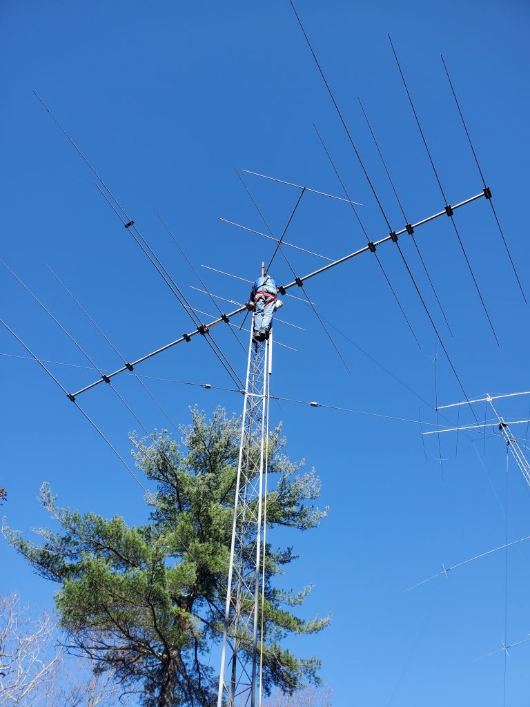
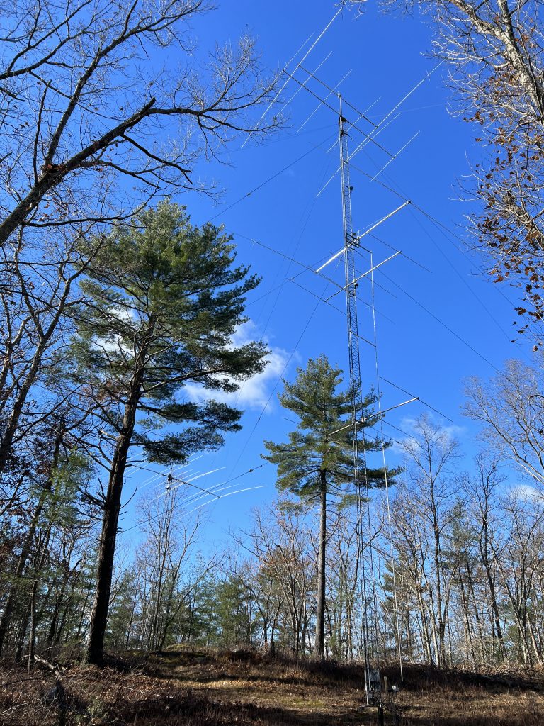
One final view of the completed installation.
Postscript
The manual doesn’t say, but you need a coil around 1.5 uH. It’s around 4 turns and 2.5″ OD. Use https://hamwaves.com/inductance/en/
One can’t really use NEC (even NEC4) to re-optimize this in a way that you could be sure that your new dimensions (keeping the spacing the same, which you can’t easily move) will yield an accurate real world result. The reason being is that NEC can’t handle elements this close together – mainly the 20m driven and 15m parasitically coupled driven element.
It’s not that it probably can’t be improved (mainly I mean the 15m SWR), but it can’t easily be done by working up a remodel via NEC like you normally would. On tribanders like this, you must keep the driven elements at least 18 inches or so from one another to keep from stressing the NEC model accuracy. That said, I believe there is an empty element bracket further back (towards the reflector) and if it was me, I’d move the 15m to that one, string a phasing line across the three driven elements and feed the 20 meter element instead. You could probably work up something a bit better that way, design it all for 50 ohm (get rid of the hairpin).
Scott, WU2X