Tower Replacement Project Part 2
This is a continuation of the story of my project to replace one of my ham radio towers. Read part 1 first.
July 23, 2022
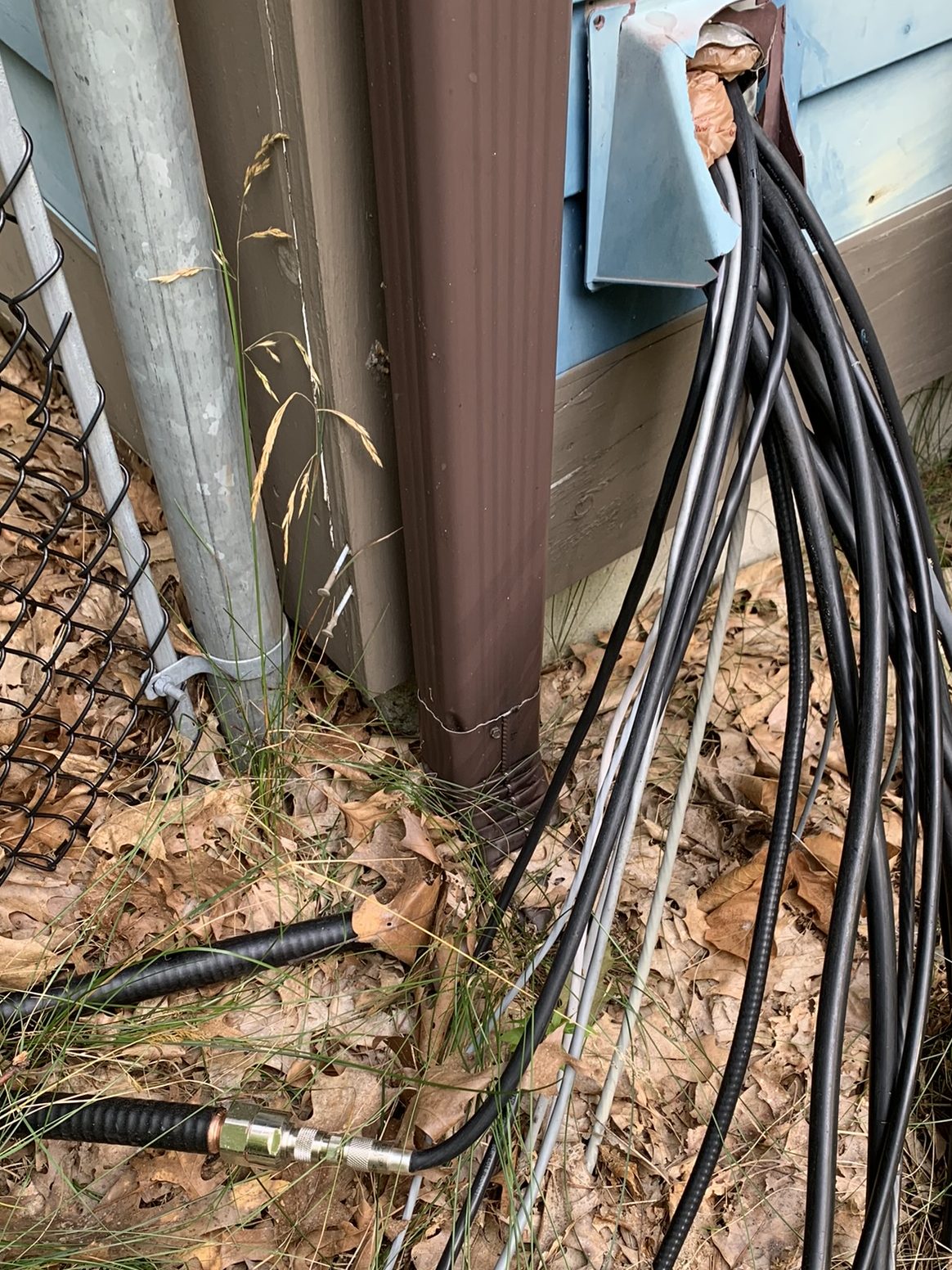
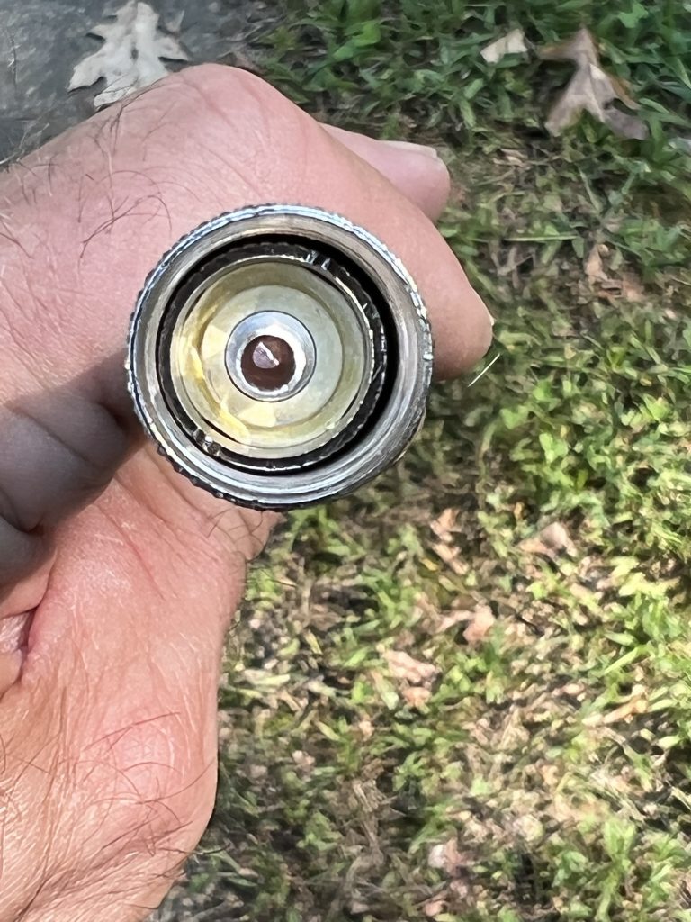
I got a great deal on some LDF5-50A 7/8″ hardline. It arrived in two pieces, but as luck would have it, they were both perfect for what I needed. The 240′ run got to the base of the new tower. The 290′ run got to the base of the tower with the TH7, A3WS, and 6m beam.
Needed connectors and found some on e-Bay. Minimal instructions. Finally found a manual from Andrews about installing connectors that filled in some of the gaps. Took me a few tries to figure out the proper way to install them. Hoping the hardline will provide a significant improvement in loss over the previous 75 ohm CATV feedline.
July 24, 2022
I continued working on trying to convert the two and a half used 40-2CD antennas that I had on hand into the making of a new one. The biggest challenge is getting the driven element separated from the insulator (used a hammer), and getting the reflector and boom pieces apart.
Then I washed everything and started reinforcing per the W6QHS article recommendations. Having the extra element pieces was very helpful.
August 13, 2022
Finally got all the bits and pieces together to make a complete 40-2CD with heavy-duty reinforcement. Assembled everything at the 5-foot level on the tower.
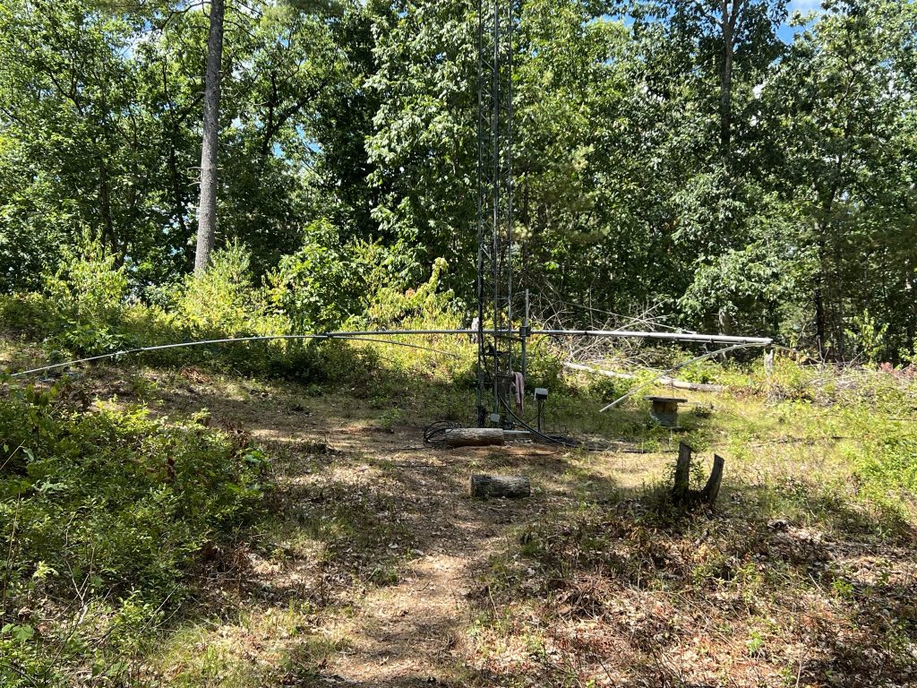
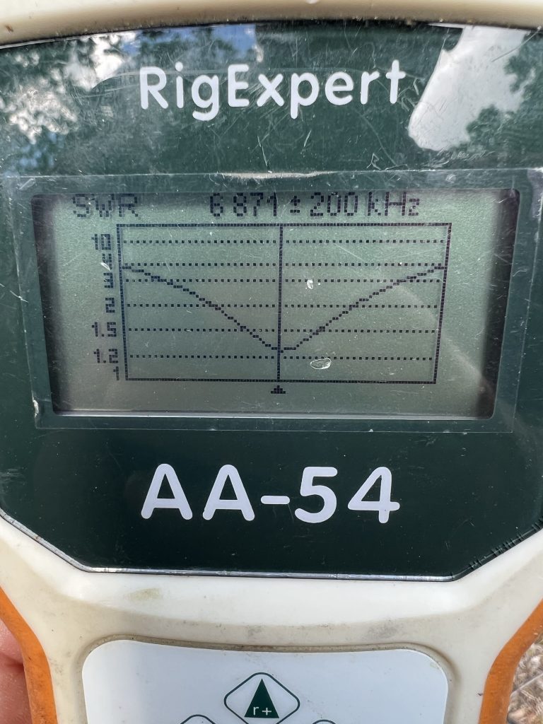
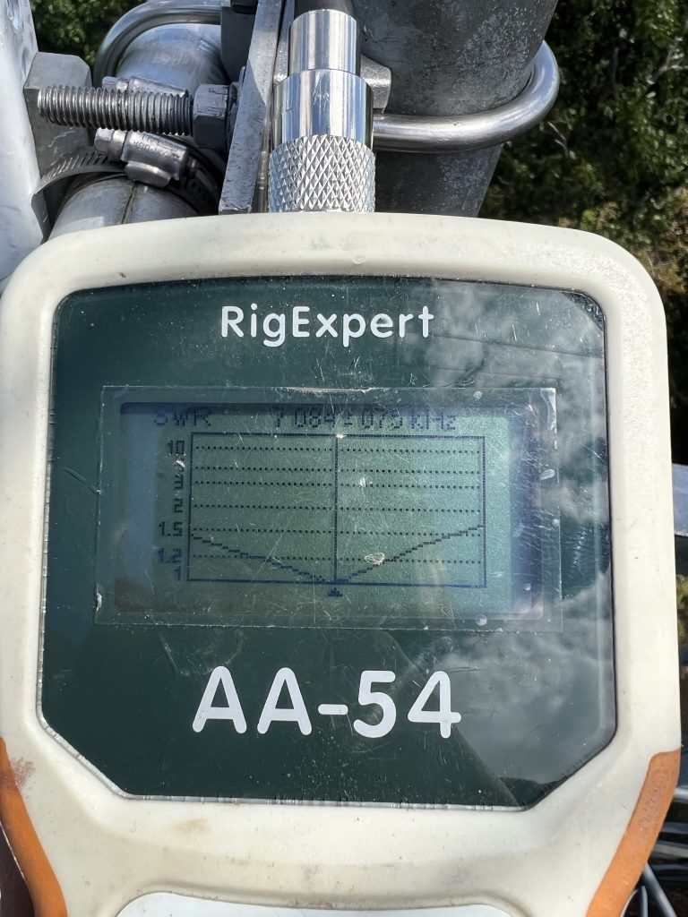
Grabbed the AA-54 to check the SWR and was happy to see it look very similar to how the first antenna did when it was at the same mounting height.
August 14, 2022
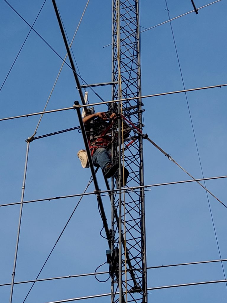
Mark KA1YQC and John KF1KI arrived on a beautiful Sunday morning to help with the antenna raising. The first order of business was to remove the 4-ele 10 that had been installed at the 70′ level. After several evenings of studying plots using the HFTA Software that comes with the ARRL Antenna Book, I realized that the 40 needed to be at that height. The two 10-meter beams were better off lower on the tower.
You hate to go backwards on a project, but it seemed easier to take this antenna down rather than try to work around it.
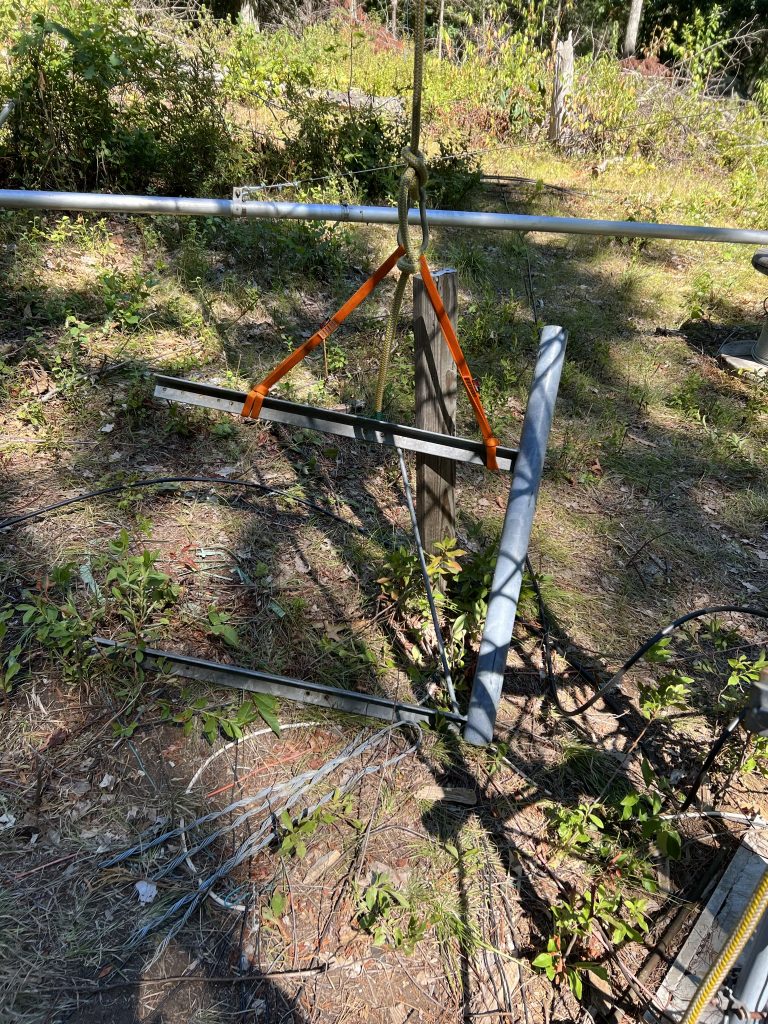
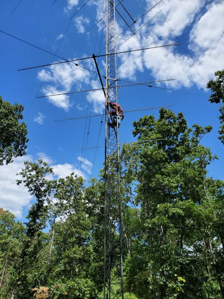
The next step was to raise the side mount that would hold the lower 40.
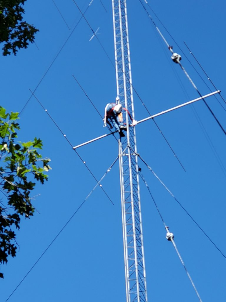
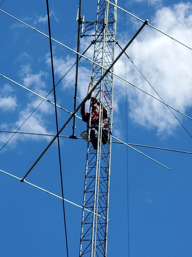
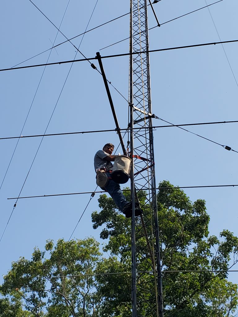
Then it was time to raise the 40-2CD. We thought about using a tram, but it seemed like it might be more trouble to set up than it would save in time. Decided to corkscrew the antenna through the two sets of guys. This was complicated a bit by a close tree that snagged the elements a few times.
John and Mark did a great job of lifting and lowering as needed. And watching for times when the antenna would snag something behind my back.
Happiness is finally getting the antenna onto the side mount. The reflector was clear of guy wires and trees, but the driven element was much closer to the guy wires than I had expected. The use of Phillystran for the guys will prevent any performance issues, but we don’t want the antenna rubbing the guy wires in the wind or under snow load. Might have to raise the antenna couple of feet to get more clearance. Something to keep an eye on.
I was anxious to check the SWR now that the antenna was in position. It dipped exactly where I had hoped!
Nothing like coming down the tower and being able to take that first look back up to see the results.
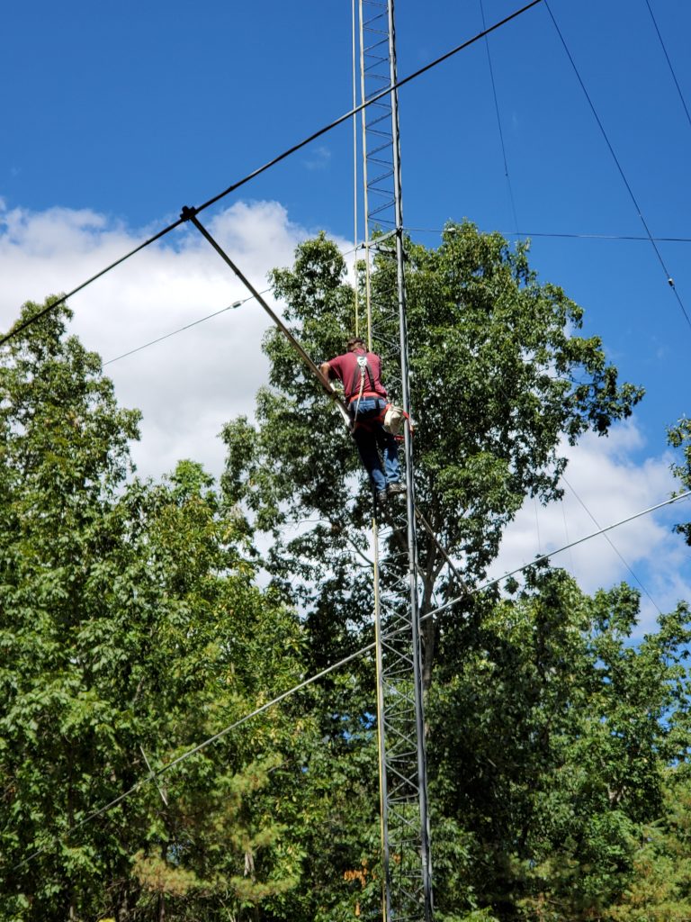
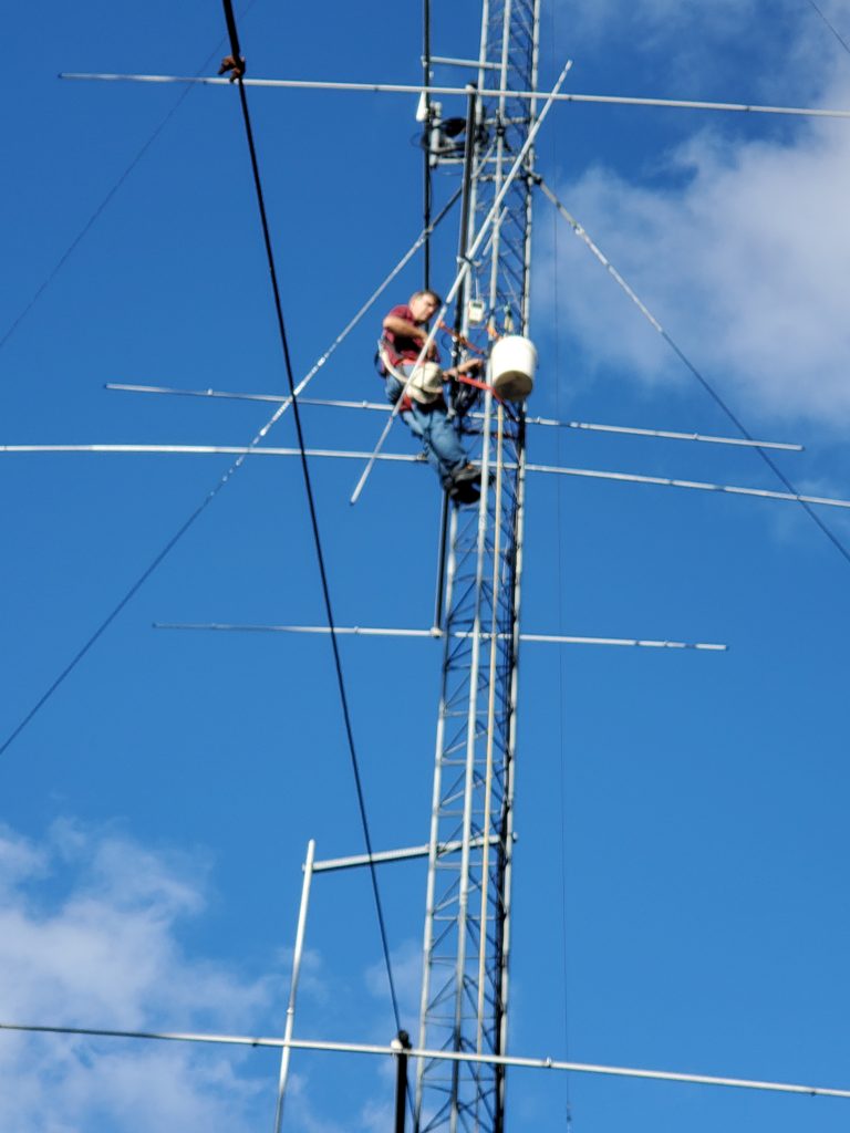
It was only noon so we moved on to raising the two 4-element 10m beams into position. This was a piece of cake compared to the 40!
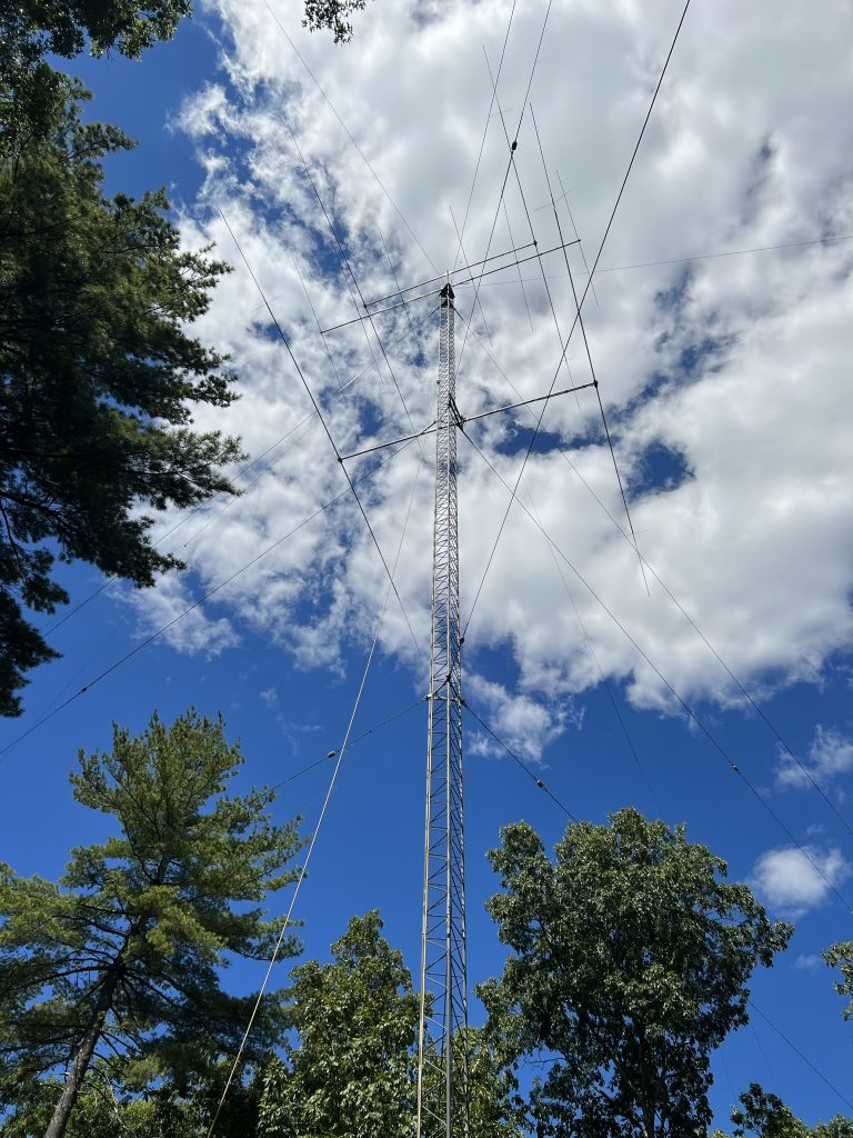
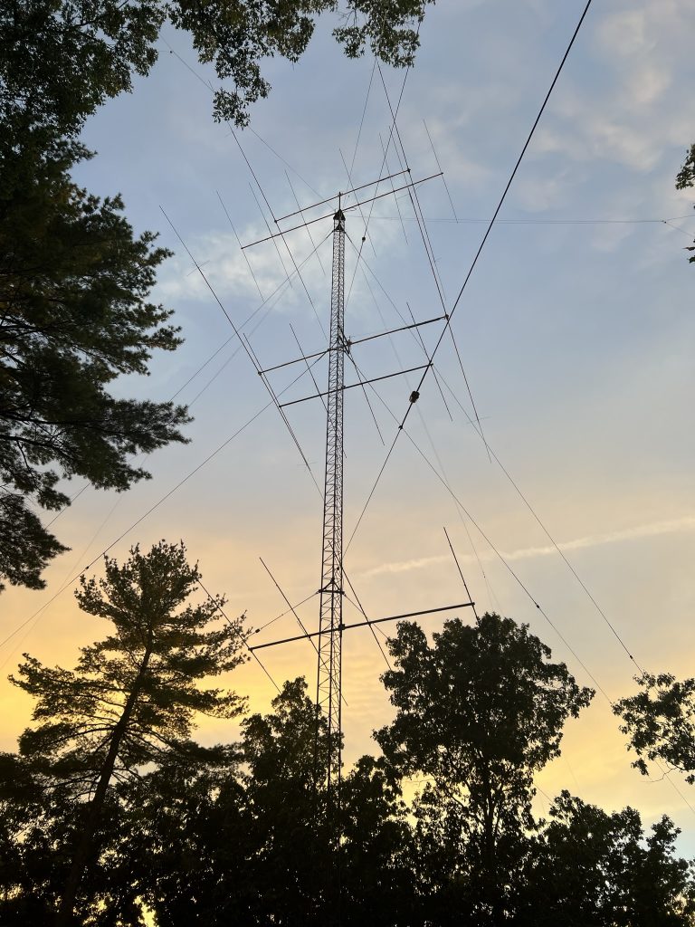
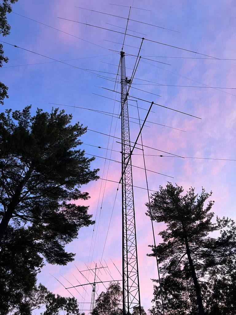
With all the antennas installed, we called it a day. I came back out to the tower later that evening to see a beautiful sunset that really highlighted the full antenna compliment.
August 21-30
Worked on making the phasing lines for the 40m stack. Will write a separate blog post on that topic.
The stacking switching is fairly simple and uses just coax phasing lines.
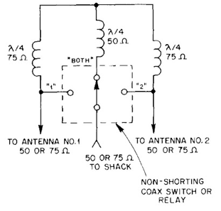
Switching uses an RCS-8V 5-position remote coax switch that I purchased used from W1DXH. The RCS-8V can be easily modified to have any of the switch positions be shorted or open when not selected. Will use some existing rotator cables to get the needed 6 conductors from the box back to the shack.
September 2
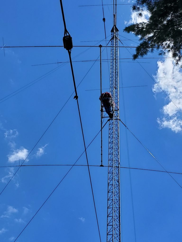
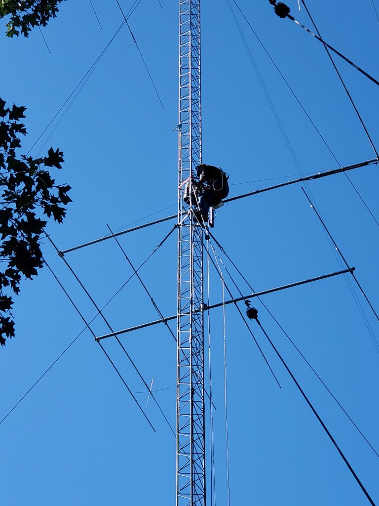
Mark KA1YQC came over to help me get the cables and relay box installed for the 40m stack. Not a hard job, but nice to have someone on the ground to send the cables up as needed.
Replaced the temporary coax from the top 40 with a piece to get to the switch box.
Installed the switch box.
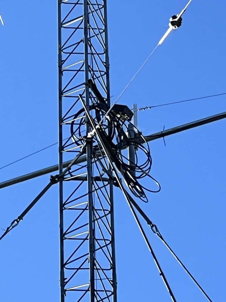
Installed the phasing lines. For now, they are just coiled up and tied off. Wanted to make sure things were working before tying things off.
I wanted to have equal lengths of feedline for each antenna. And for those lengths to be a multiple of a 1/4-wave. That means the low antenna has about 50′ of extra coax, but it worked out great for getting down from the top antenna.
We wired the control line back to the shack and were prepared to see success. The top position worked. The lower position worked. But not both. Argh. Checked the control voltages and they were correct going up the tower.
Climbed the tower to inspect things. Discovered the t-connector had failed. Argh. It is the one that has 3 female UHF connectors that ties the 3 phasing lines together. A new t-connector is now on order. (I should have known better than to use a cheap one I found in my junk box.)
The good news is that listening to Europeans in the early evening shows the low 40m being the best antenna at times. Will be interesting to see if/how this changes as we get into the contest season and operate the whole opening from our sunset to European sunrise.
Checked the SWR on the two lower 10m beams. The middle one looks ok. The bottom one is resonant way below the band. Could be interaction with the metal guy wires that are within inches of the elements. Will do more work with HFTA to see if that antenna can be moved up or down the tower.
September 4, 2022
While waiting for Amazon to deliver, I went up the tower and refactored all the coaxes around the 40m switch box. With a few days of rain in the forecast, I wanted to get all of the connections secured.
Amazon arrived while I was on the tower, so with the sun just going over the horizon, I made one more trip up the tower to install the new t-connector.
Argh. Still a problem with the both-position on the switch. And to make things worse, the high antenna only wasn’t working either.
September 7-9, 2022
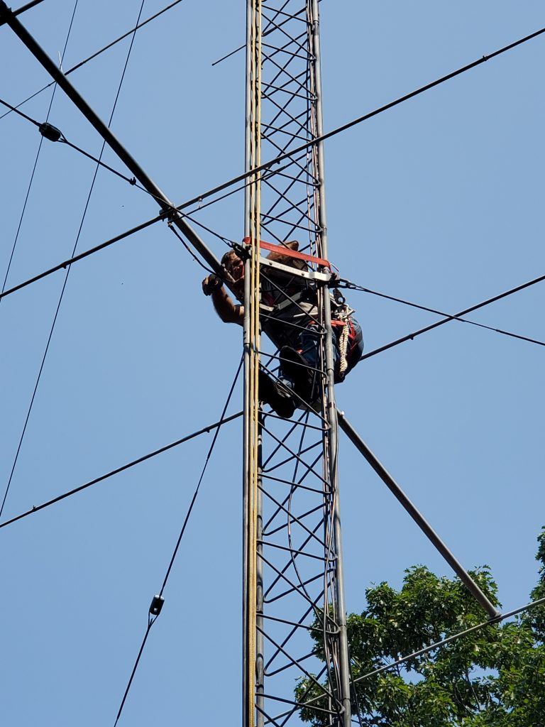
Multiple trips up the tower to try to diagnose the problem. I probably made 6-8 climbs to the 70′ level and was up there for several hours. Just couldn’t make sense of what I was seeing.
When checking the wiring, I discovered that a wire had pulled out of the splice junction at the base of the tower. That fixed the antenna 1 problem.
I got some good advice from W2SC and N2NT on things to try for the phasing lines. Eventually tracked the problem down to a missed solder connection on one of the PL-259 connectors! I usually solder the shield and then wait for the connector to cool before doing the center conductor. Somehow I missed doing this one.
When you test quarter wave coax lines, you look for an open on the analyzer. When I checked the cable from one end it looked fine. But, if I plugged the analyzer into the end with the missing solder, it showed there was no cable. I guess you have to test phasing lines from both ends…
Once I found and fixed that, I was happy to come down to the shack and hear all 3 positions of the stack were working. SWR was good from 7000 to 7250. All positions of the new stack are better than my original 40-2CD on another tower. (It must have a problem?) The stack position seemed to be slightly better most of the time. Spent some time on 40 SSB in the WAE contest and the stack seemed to be a winner compared to the top or bottom antenna alone. Thrilled to finally see success after all this effort.
September 10, 2022
Mark KA1YQC came over on a beautiful Saturday morning to help me work on the 10m stacking.
We moved the lower 10 from 29′ to 32′. This got it out of the guy wires and just above the first set.
Then we installed the WX0B Stackmatch box at the 65′ level. Checked SWR on each antenna as I did so. The bottom 2 antennas are resonant below the band. Is this caused by having Rohn 45G going through the middle of the antenna? Something to investigate.
We connected the control cable and headed back to the shack to check out work. All 3 positions could hear band noise. We listened to PT5J work Europeans in WAE. May need to investigate the wiring or the box as it didn’t seem like the right antenna was being selected as I switched through all the options. But, SWR was good across the band on all 3.
The last task was to raise and reattach the 160m shunt feed. This took no time and we were pleasantly surprised to find that the antenna was resonant around 1800 Khz. I had been afraid that adding 10′ to the tower and the second 40 would change the electrical height of the system. Will wait for dark to see if the antenna works.
Really enjoying having Mark’s help to take advantage of the fantastic early Fall weather to get things done before it gets rainy, cold, and windy in October.
September 21, 2022
On what is sure to be the last perfect day of the summer, Mark KA1YQC came over to help debug the 10m stack. We quickly determined there was a broken wire somewhere in the 250′ of cable between the shack and the base of the tower. It was the line that switched the toroid in the Stackmatch out when feeding a single antenna. No wonder the SWR and antenna selection was so weird. We grabbed a spare wire from the control cable to the 40m switching and things started working better.
The SWR on the low antennas was below 28.o Mhz. They resonated higher when tested at the 6′ level, but the extra height, guy wires, or Rohn 45 going through the middle was having an impact. We shortened the driven element on both antennas so they were resonant around 28.2, which kept the SWR relatively low from CW through 28.5 Mhz. Luckily this just meant rotating the driven element so both ends of the element could be reached from the tower.
Testing from the shack indicated there was something wrong with the low antenna. It sounded quiet and the SWR was height. We know the SWR was good using the antenna analyzer at the feed point, so it has to be in the coax or the Stackmatch. No amount of wiggling or unscrewing seemed to make any difference. So more diagnostic work needs to be done.
We also tried to find the tap point for the 160 shunt feed. We thought we had it, and then realized we did not have a solid connection from the feed point shield to the tower. When we added that, the R value was around 18 ohms. The tap point needs to be raised, but with sunset approaching, we decided to save this for another day.
October 12, 2022
One more very nice weather day. Mark KA1YQC came over and we attacked the 160m shunt feed. After some experimenting, we determined the shunt wire could not go through the 40. We attached it just below the 40 and were able to get it about 5′ out from the tower to get to 42 ohms. SWR is < 2:1 from 1800 to 1880 with a perfect dip at 1830.
The First 160m QSO with the shunt-fed tower was with TO2DL in Guadeloupe (FG). At least now I know it can be heard.
Project Complete!
The project is officially done. All new antennas have been installed and the others restored to their previous configuration.
Early results show the 40m stack is much better than my previous 40-2CD on the other tower. The 10m stack also seems to be working well. Finding the broken wire may have been all it needed.
Now the fun part – to get on the air and see how it all plays in the contests.
Thank you all for following the journey to this point. It has been a lot of work, but the kind that I really enjoy. Nothing has more hope than a new antenna system!