EFHW Basics
I don’t think I had ever heard of an EFHW (End-fed half wave) antenna 5 years ago. Now they seem to be in use everywhere. They are a compromise multi-band antenna, but they seem to work well enough that people use them.
In a follow-up email exchange, Ward Silver, N0AX, provided this information on the EFHW that was new to me.
The key to getting the most out of an EFHW is the impedance transformer and how you install the antenna.
Transformer design was all over the place until K1RF published a really good presentation on his effective design. (http://gnarc.org/wp-content/uploads/The-End-Fed-Half-Wave-Antenna.pdf) Summarizing, you have to use the right ferrite and have an end-fed impedance that is reasonably close to what the transformer can be expected to match. The ferrite has to be in its inductive (low-loss) region because it’s a flux-coupled transformer, not a transmission-line choke. Type 43 works well across the HF spectrum, becoming lossy above low VHF where it is used for EMI suppression. Using Type 31 makes the transformer an RF sponge at HF which is what it’s designed for. Turns ratios making the impedance ratio anywhere from 9:1 (3 to 1 turns) to 81:1 (9 to 1 turns) are used but the ratio most suitable to a wide variety of feed point impedances is 49:1 as I explain here: https://www.onallbands.com/feeding-end-fed-antennas/ Not having enough core cross-section area for the power level involved (1.5″ OD for QRP, 2.4″ OD for 100W, 2×2.4″ OD for up to 500 W CW or 1 kW SSB, 3×2.4″ OD for 1.5 kW) drives the core into a lossy region and it heats up.
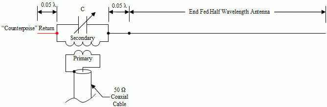
Having some additional conductor beyond the feed point – I hesitate to call it a “counterpoise” because that’s not what it is acting as – helps stabilize the feed point impedance. This is usually the outer surface of the coax. Using a current choke at the feed point blocks this path and makes the feed point impedance erratic so it’s kind of a crapshoot how the SWR will look. If the feed point transformer is up in the air, such as in a horizontal configuration, the length of coax starts to become more significant and the antenna starts to look like an OCFD. Depending on how much coax surface there is, the resulting feed point impedance can also become erratic. The most reliably effective installation is to put the transformer three to six feet above the ground, run the wire straight up with a non-metallic (fiberglass) mast for at least 10 feet, then run the wire up to the highest point you can find so that it’s basically an inverted-L. Just lay the coax on the ground – it will be fine and non-fussy.
True, the EFHW only “requires” one support, but so does a dipole as an inverted-V or sloping dipole. The important thing is where the current maxima are located with respect to ground. This changes with frequency. On the lowest two bands, the current maxima are in the middle half of the antenna. On the higher bands, the current maxima are all across the antenna with the higher peaks nearer the transformer. The higher the maxima above ground, the more efficient radiator the antenna will be. On 15/12/10 meters, an 80-10 antenna starts to look like an end-fed long wire and radiates in the direction away from the feed point.
A center-fed doublet will work just as well but you have to have an antenna tuner for the even harmonic bands and use a low-loss open-wire line between the feed point and the tuner. Note that using 100 feet or more of RG-58 with the “wrong” transformer or a funky installation will make an antenna look just dandy to the transmitter due to feed line loss. If the coax-fed EFHW is presenting an SWR high enough to require a tuner at the transmitter, something is wrong either in the design or installation. You may be able to get a match with the tuner but feed line loss is likely to be high – you can hear people but not work them.
Most folks don’t really understand the antenna, install it any old way or really low, have unreasonable expectations, and are disappointed. Or the manufacturer doesn’t use the right ferrite or provides the wrong impedance ratio, or, or, or and the antenna just isn’t efficient. The result is unhappy customers who need education – sometimes “app notes” will really help.
Ward Silver, N0AX, email dated June 26, 2024
I found the information above informative and asked Ward if I could share it so others might benefit. Hope you find something that helps you get the most out of your EFHW antenna.