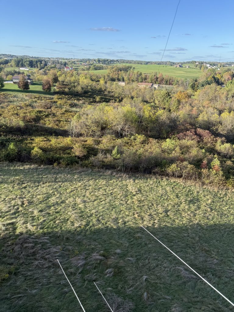
No trees. A property that mostly went down into a valley. The choices for the low bands were limited. I had hoped to shunt feed one of the towers on 160, but the short heights and side mount antennas made that unlikely. Back to basics.
October 14. 2025
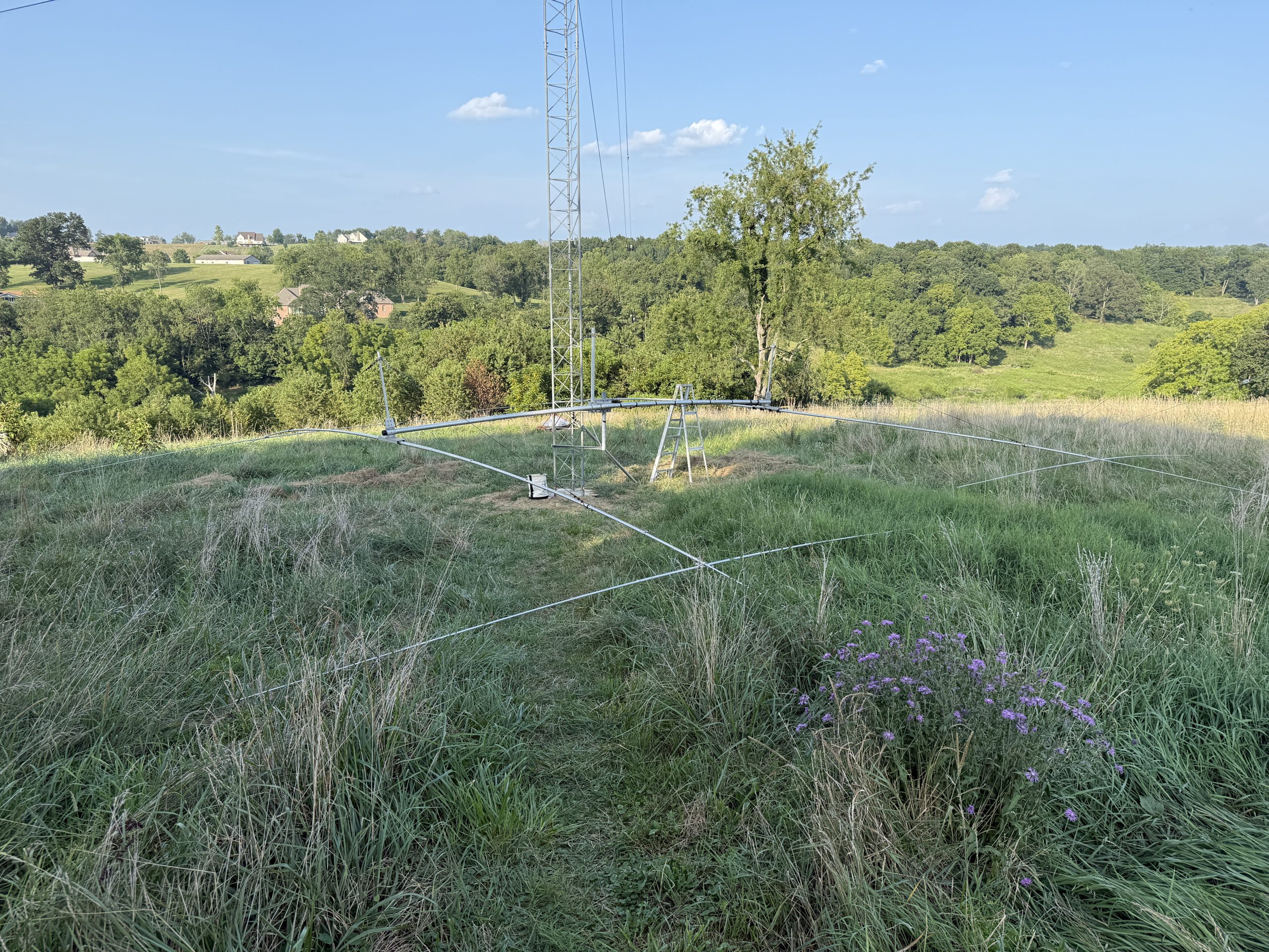
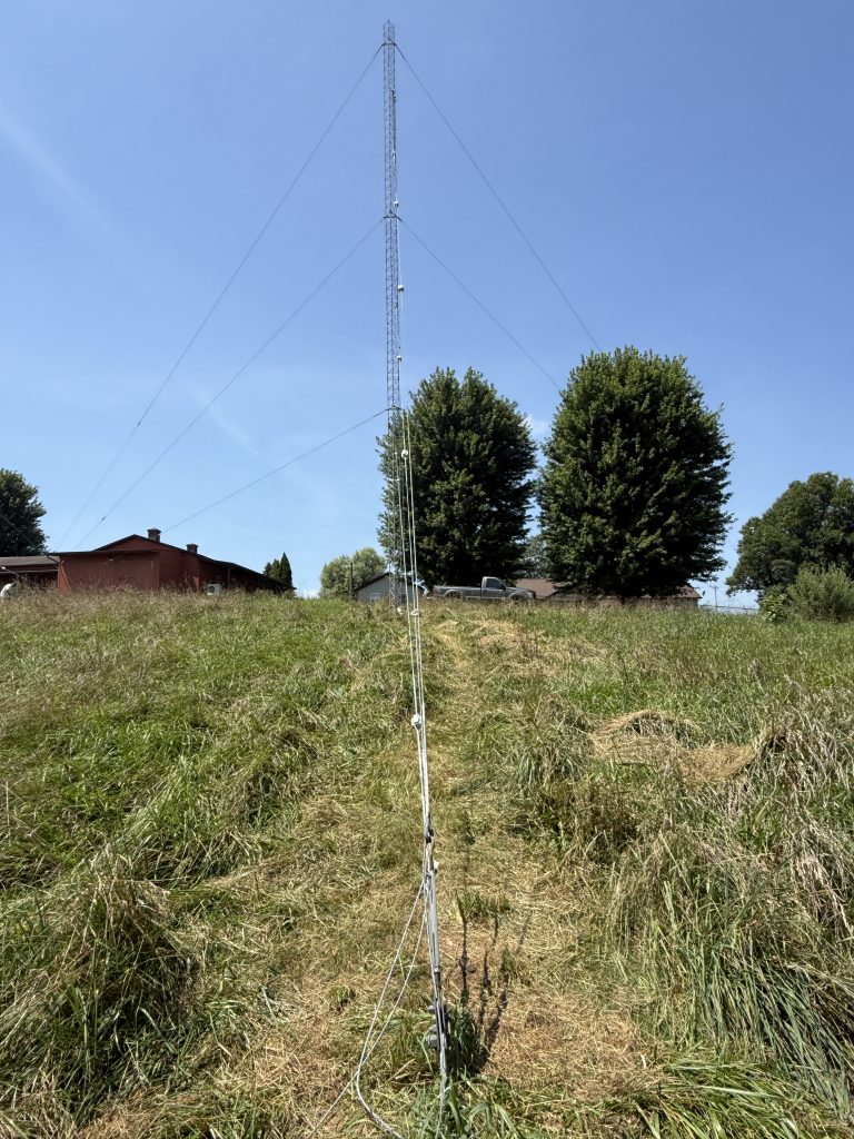
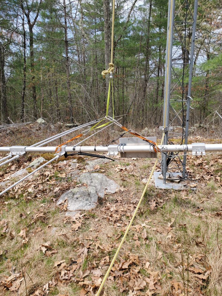
80 meters
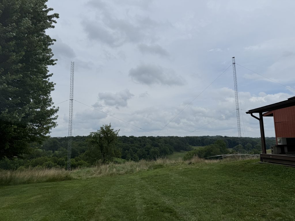
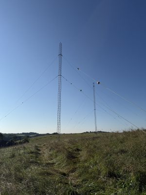
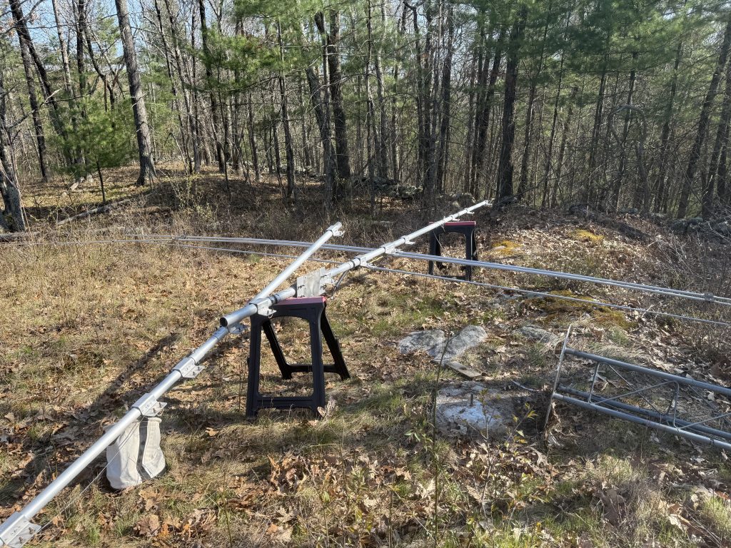
The two towers are 100 feet apart. That would work well for one half of a dipole. The other side was empty land with some trees. It was an easy choice to put up a dipole with its feedpoint on the North tower. The coil of coax at the tower was a crude attempt to make a choke.
Wires going north and south.
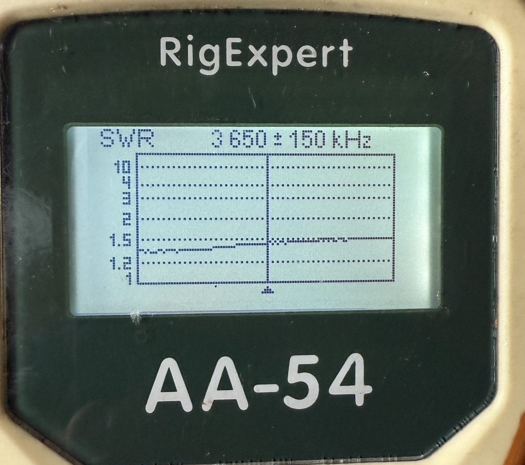
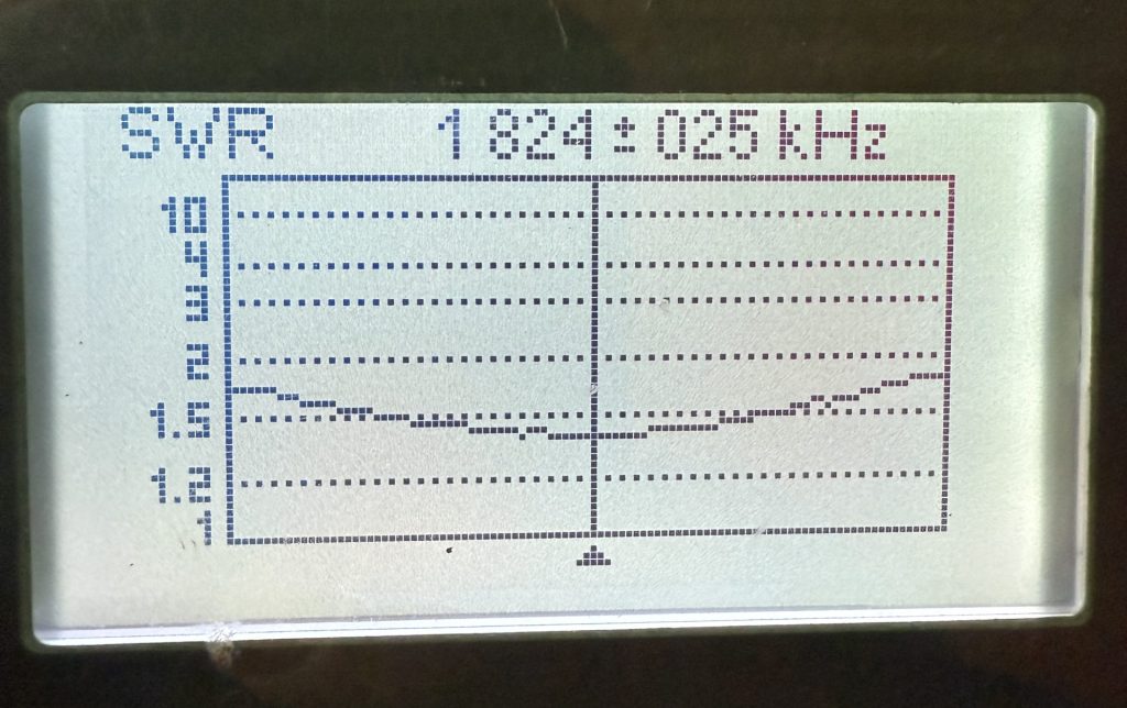
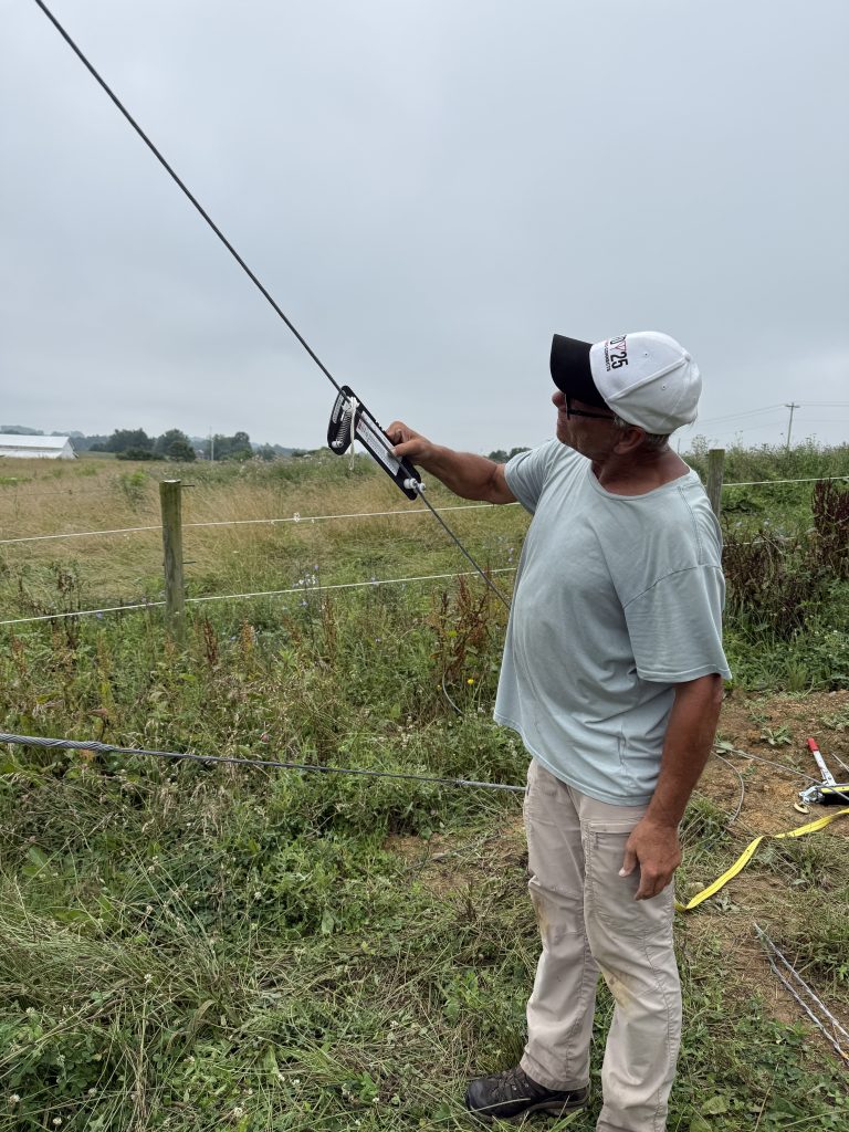
What is amazing about this antenna is the bandwidth.
This is accomplished using some tricks with coax that were presented in a September 1983 QST article by Frank Witt, AI1H. “A Simple Broadband Dipole for 80 Meters.” I had similar results with this antenna and the same feedline when I was in MA.
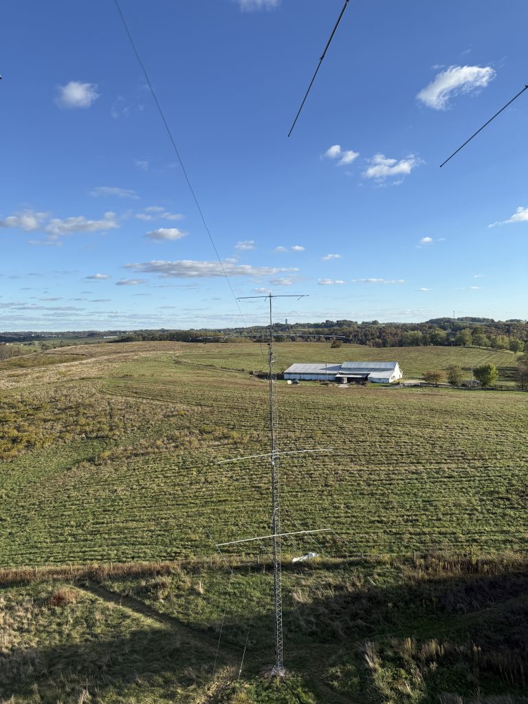
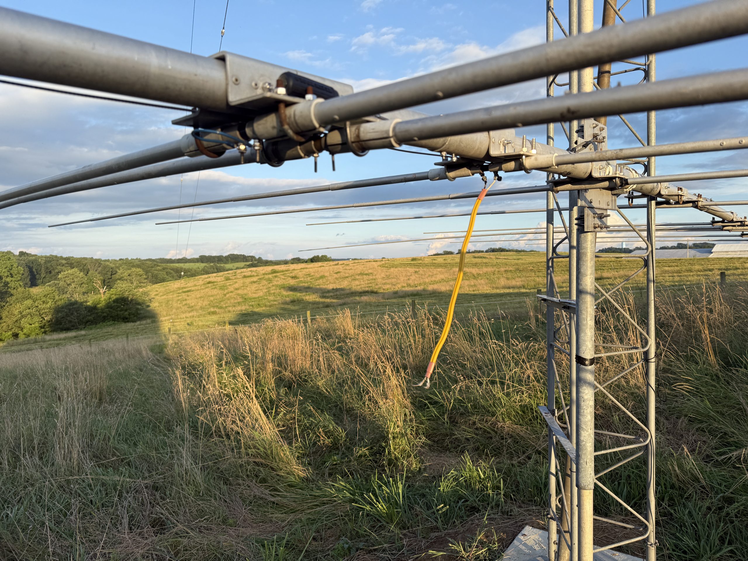
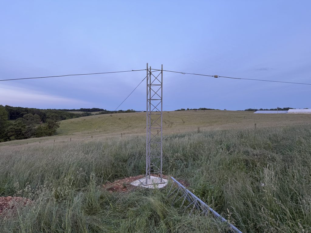
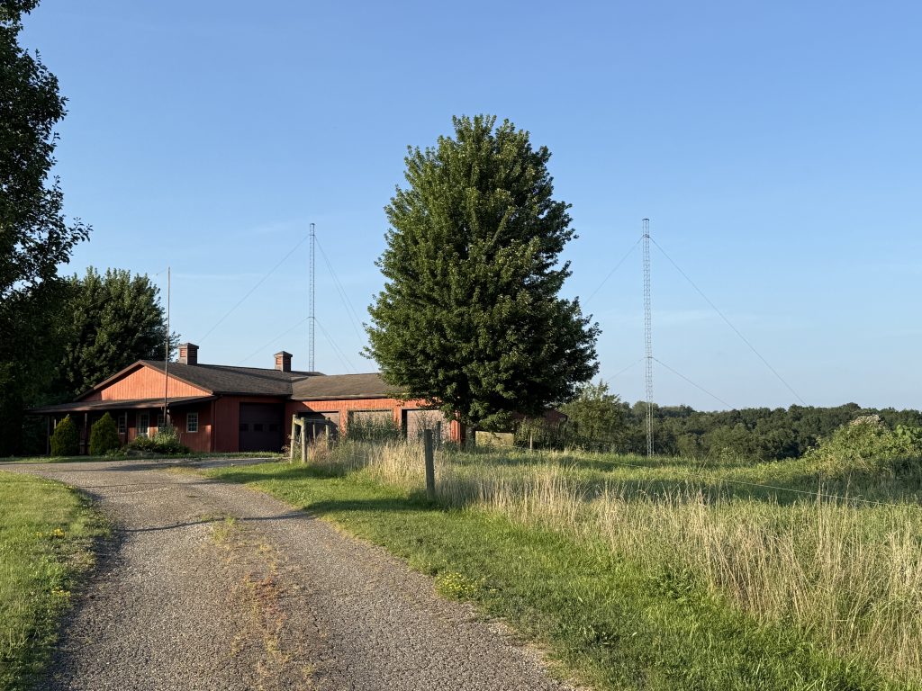
160 Meters
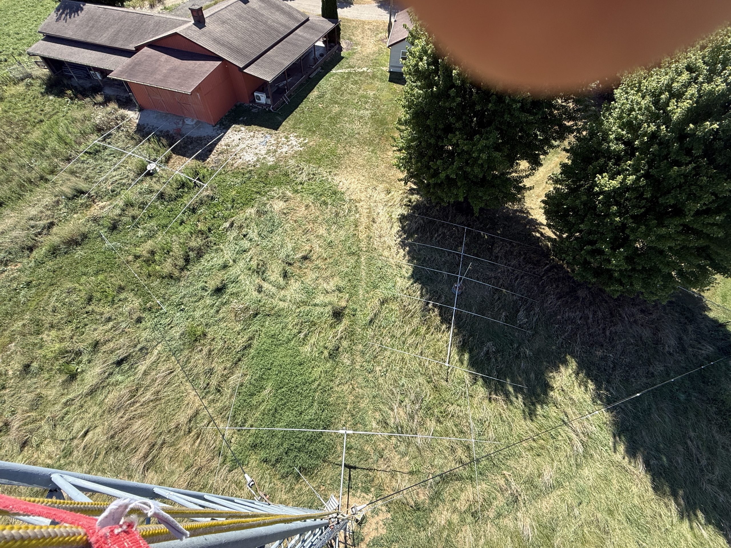
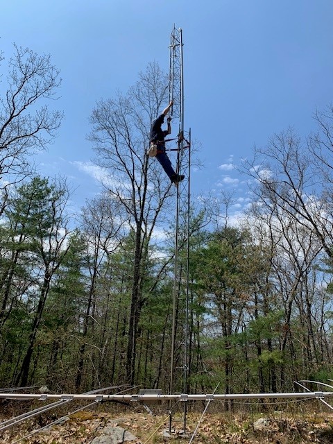
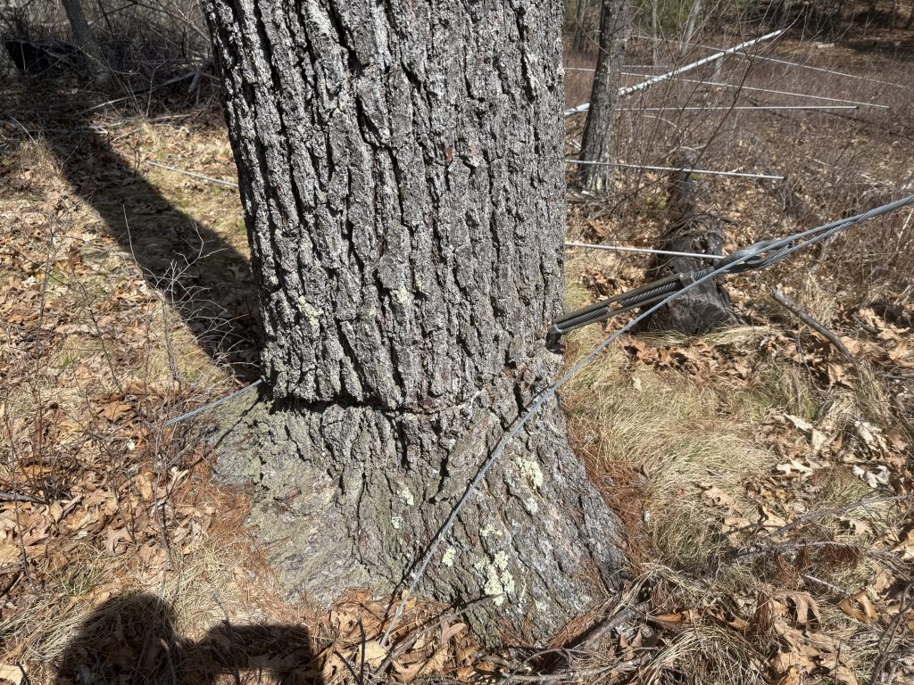
I didn’t want the 80 and 160 antennas to be any closer than they had to be. That meant the 160 antenna had to hang from the South tower. I had a tree at the bottom of the property to the north east and another tree to the south east. No choice but an inverted Vee with the ends elevated as much as possible.
I originally put this antenna up without a choke. The SWR was narrow and it just didn’t seem right. Adding the choke calmed things down. The SWR curve is not great, but it let’s me work people.
The station is now active on all the HF contest bands and ready for ARRL November Sweepstakes and then CQ WW CW.
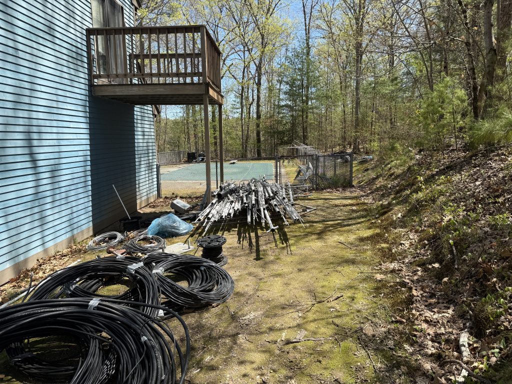
Getting the antennas on the tower was almost the easiest part of the job. It felt like it took days and hours to get the necessary feedlines and control cables connected.
Public Service Announcement
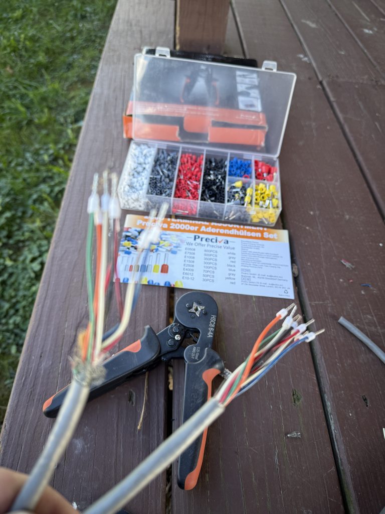
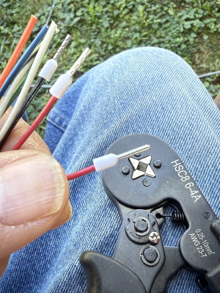
Over the summer, I heard about a Ferrule Crimping Tool Kit. I had never heard of this tool before, but it changed the way I made control wire connections in the station. All those little strands of wire are captured in the ferrule, and much easier to connect and stay connected.
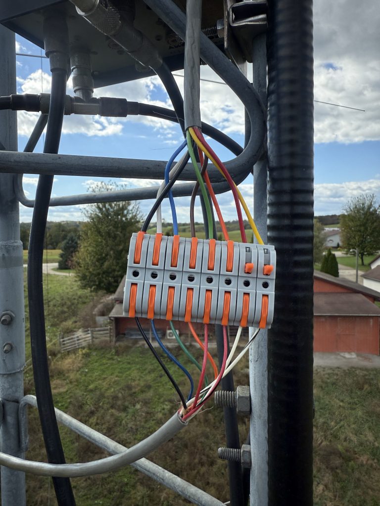
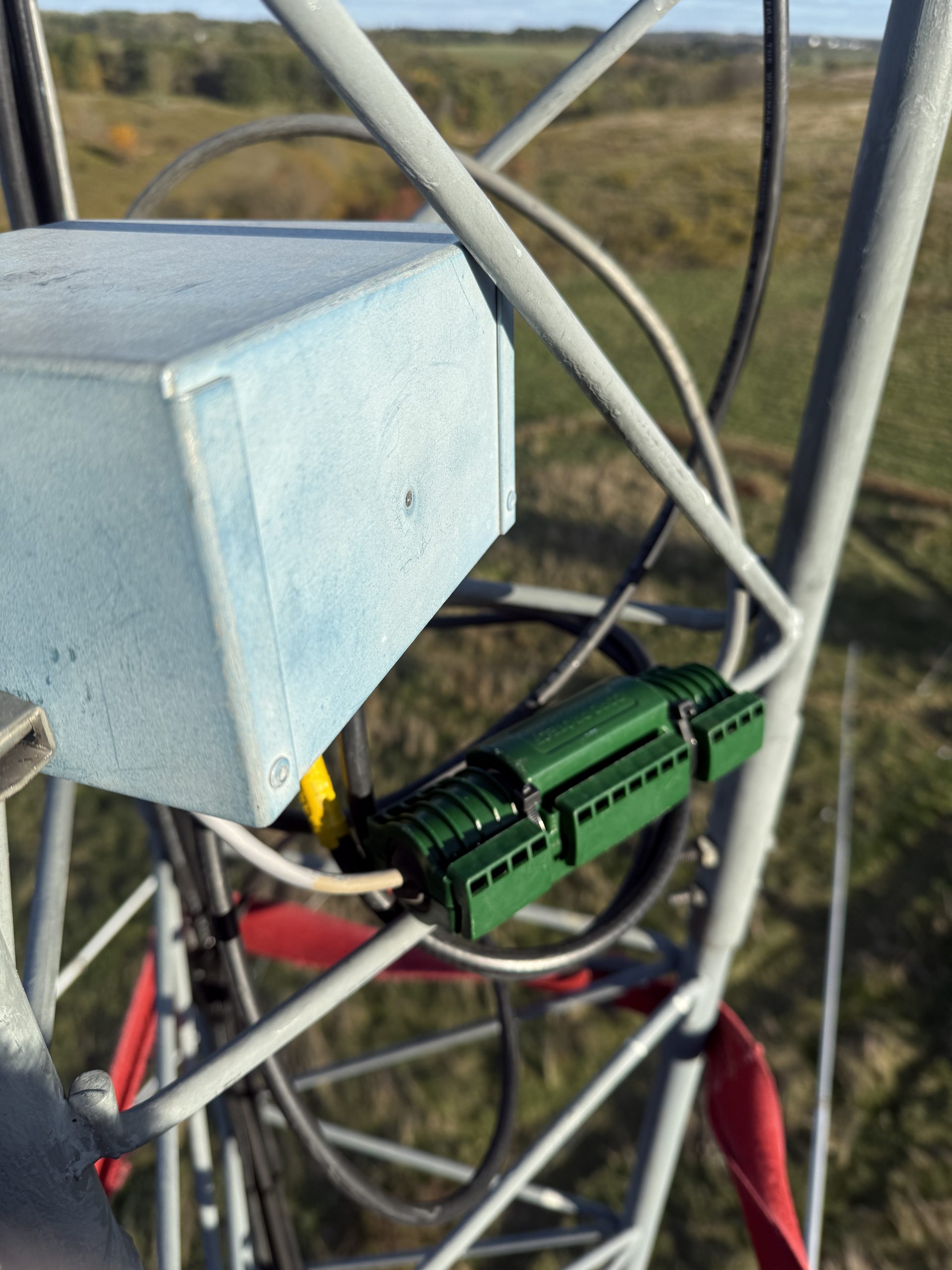
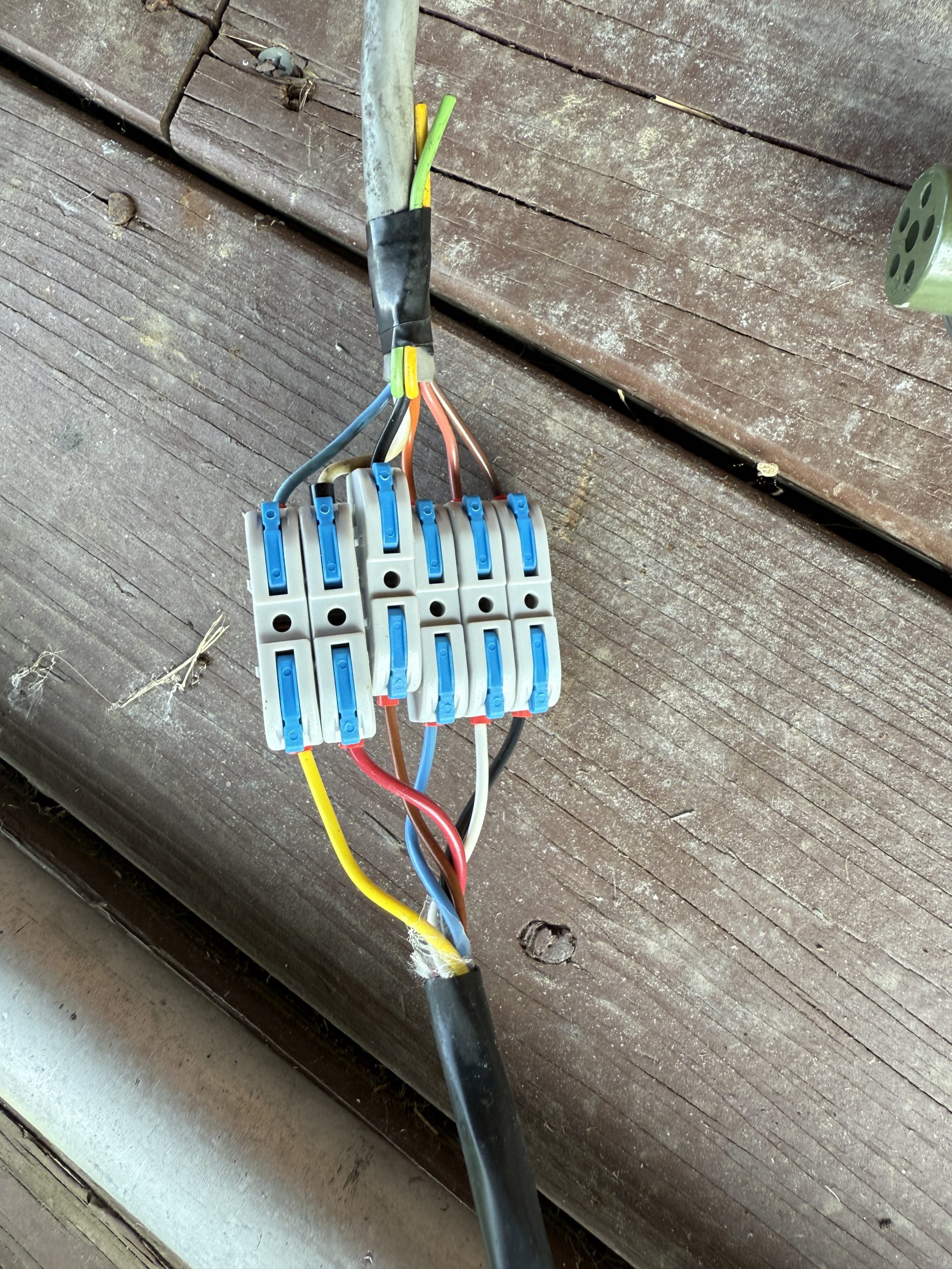
I am also a big fan of these European connectors for making control cable connections that are easy to install. They work great with the ferrules!
August 22, 2025
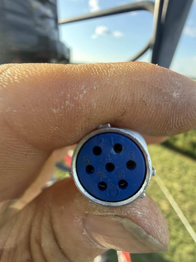
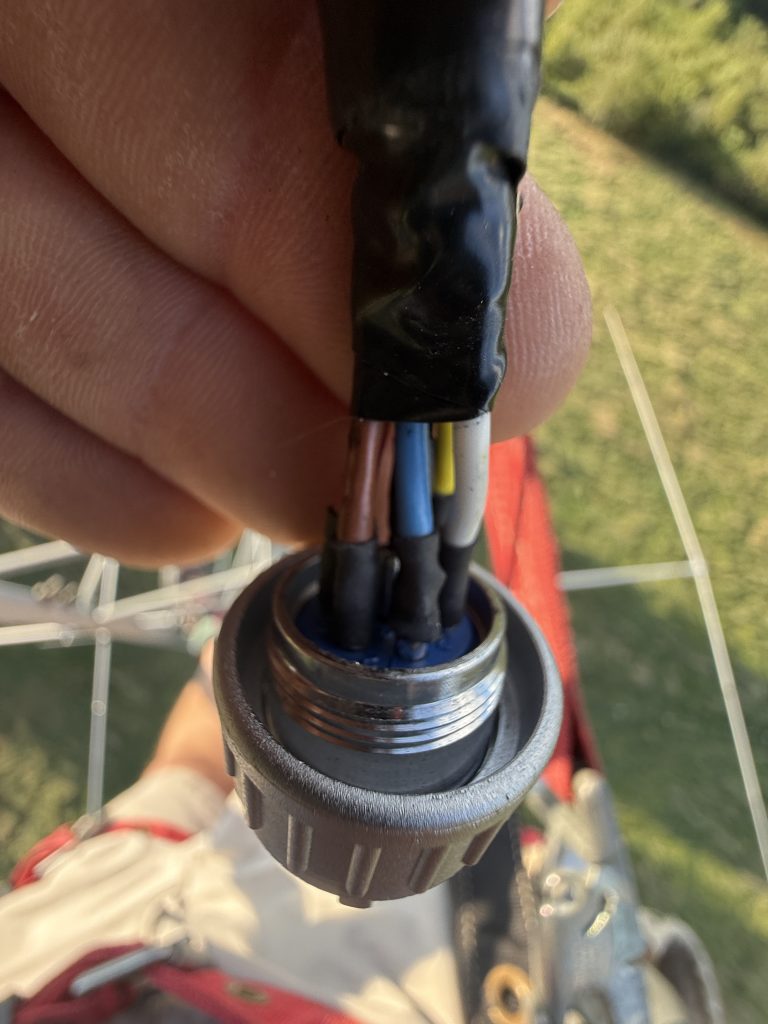
The North tower (20/40 meters) used a Yaesu G-2800 rotator. This was one I had used in MA, but had not made any notes about what colors were on what pins. When I wired up the rotator box, nothing worked. I had to climb the tower, take the connector apart, and see the colors. Argh.
This is when I started taking pictures every time I wired up control cables. It is so easy to mess up or forget the color code order. Having a photo pasted into the station notebook can save a trip up the tower.
I was happy to see the rotator turn and indicate correctly!
August 24, 2025
For a stacking box on 20, I had an early version of the Monostacker designed by W8WWV. This system enables upper, lower, both in phase, and both out of phase. It has a slightly complex set of control voltages to control the relays and requires multiple phasing lines at the box. It does work well. (A better version without the phasing lines is now available commercially from DXE).
I used some 7/8″ hardline that I already had for the home run back to the shack.
October 6, 2025
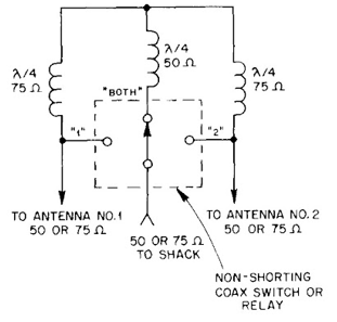
For the 15m stack on the South tower, I decided to use the same method as I had in MA.
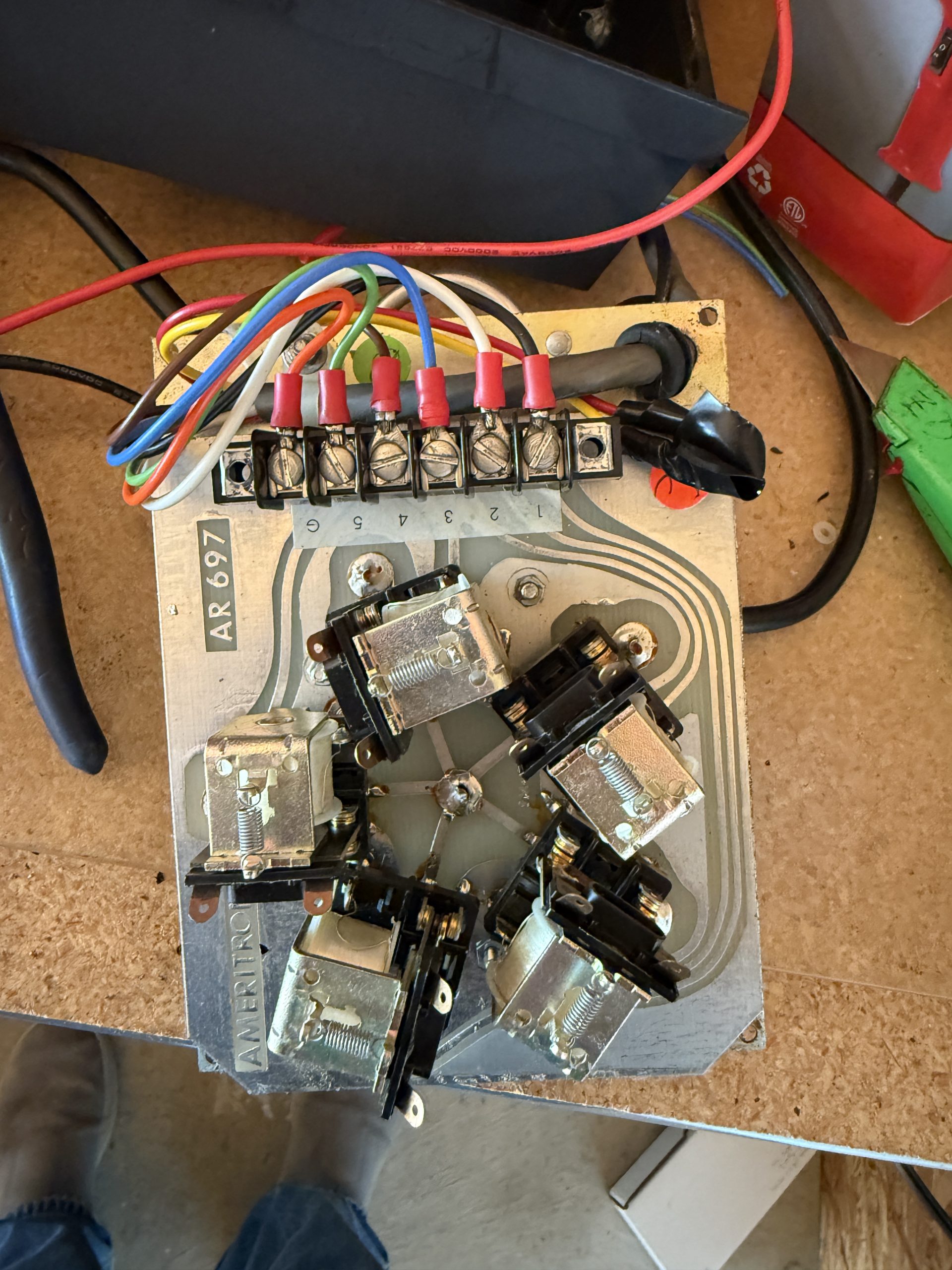
This uses an RCS-8V 5-position remote coax switch that I already had. I just had to make sure the 3 antenna selections did not ground unused relays.
It is easy to add or remove a jumper on each relay to determine if the coax is shorted or open when the relay is not energized. (This photo is an example of saving control wire connections in my station notebook.)
The 15m stack used a piece of 1/2″ 70 ohm CATV hardline that I had on hand. I don’t like having to use transformers on each end, but I already had them so it was the cheapest way to go.
Rather than try to reuse the old phasing lines, I made all new ones.
October 12, 2025
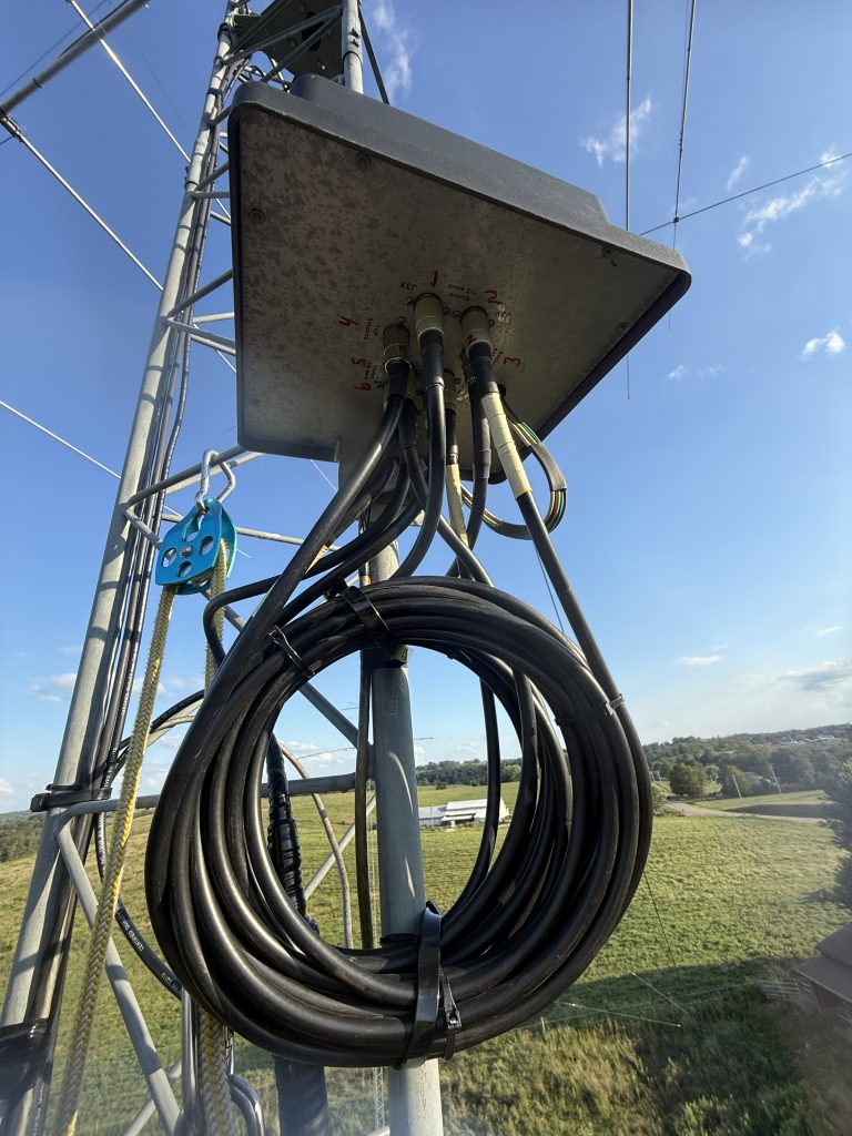
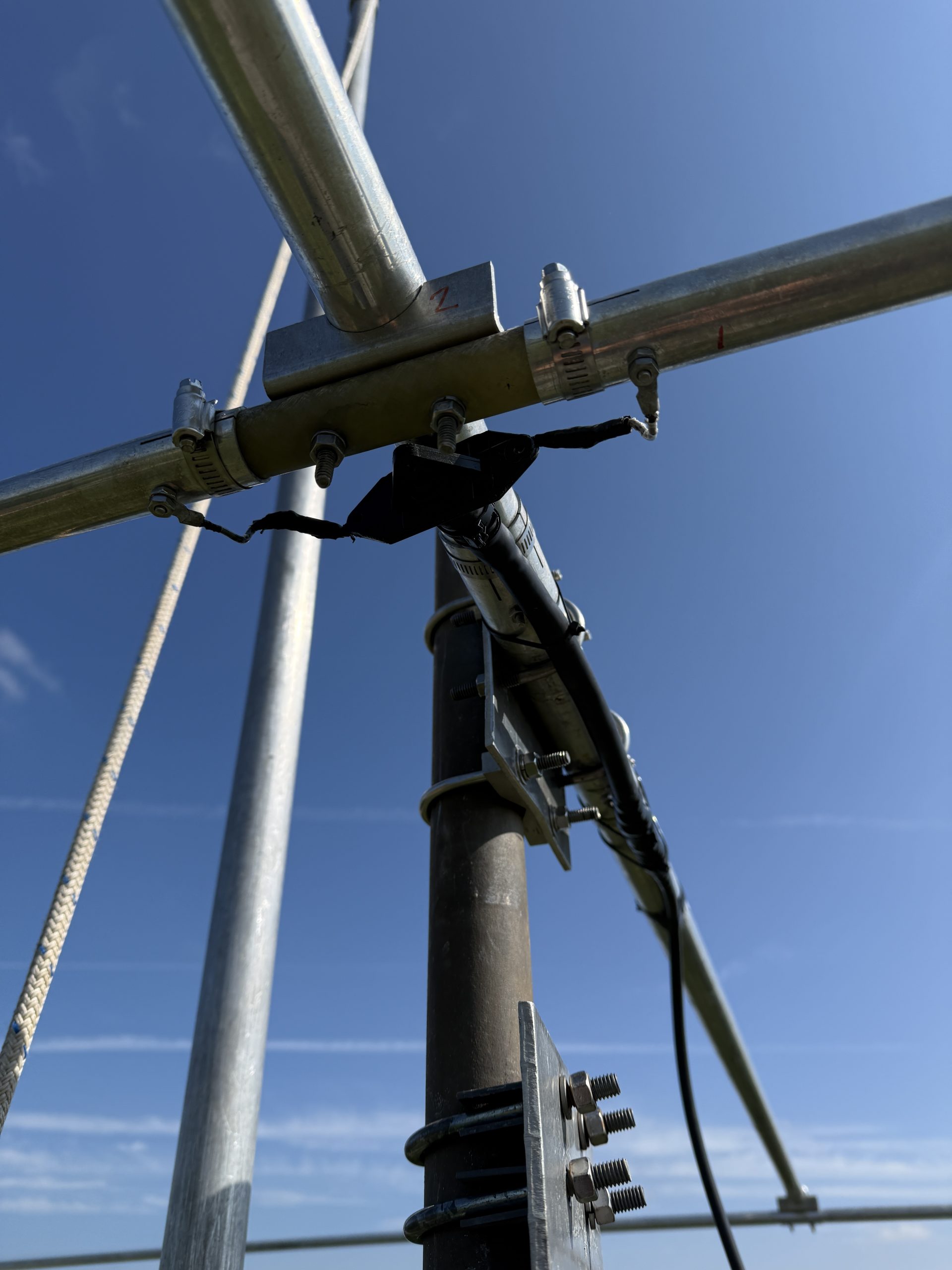
The 40m stack used an Array Solutions 3-high StackMatch. It only required equal feedline lengths from each antenna. I mounted the StackMatch on the tower and used a power cord protector to keep the connection dry.
In the left photo above you can see a problem that caused me a day of frustration and multiple tower climbs. The blue wire had come loose from the terminal block. I can’t believe I captured the error in a photo, but missed it when I was looking right at it!
For the third antenna, I added a 40-meter inverted Vee at the 24′ level on the tower. I figured it would be useful in domestic contests to have a high-angle radiator.
The 40 meter system has been one of the real surprises of the new station. The Moxon has been an outstanding performer. The stack of the Moxon and 40-2CD has been better than expected into Europe. The 3 antennas worked well in Sweepstakes with one NE, one W, and the dipole for the close stations.
The coax back to the shack was some 1/2″ 50 ohm hardline that I had on hand.
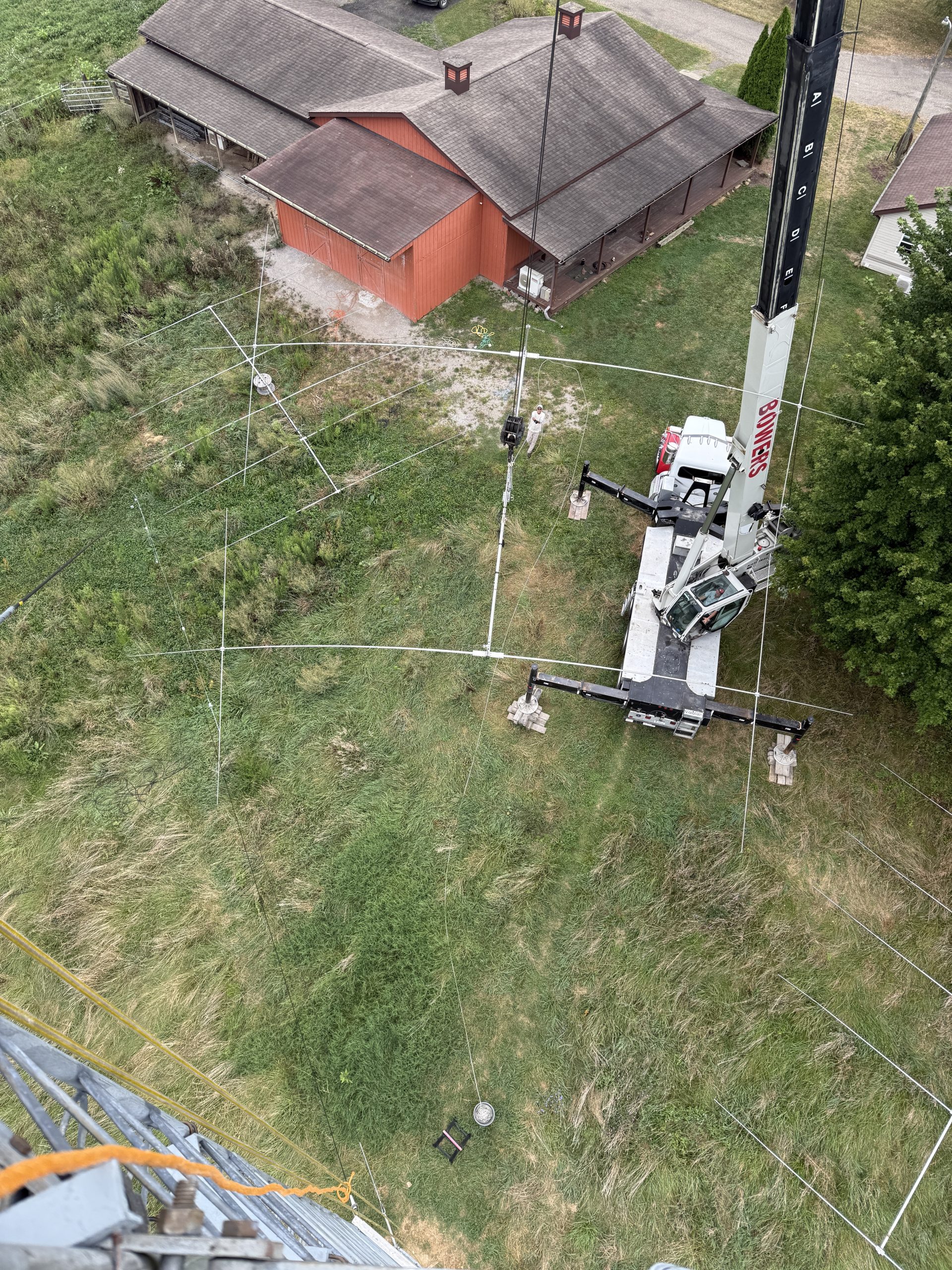
While Mike WA3C and I may have been able to get the Moxon to the top of the tower, it just didn’t seem like it would be worth the risk. Mike knew a crane company that he had used and recommended. We scheduled the date about 3 weeks in advance with the hope that the weather would be good.
With a crane, you pay from when they leave the yard until they return. You can buy 4 hours or 8 hours. It was about a 45-minute drive each. I was hoping we could get the job done quickly, but we ended up using about 6 hours. Still well worth the expense!
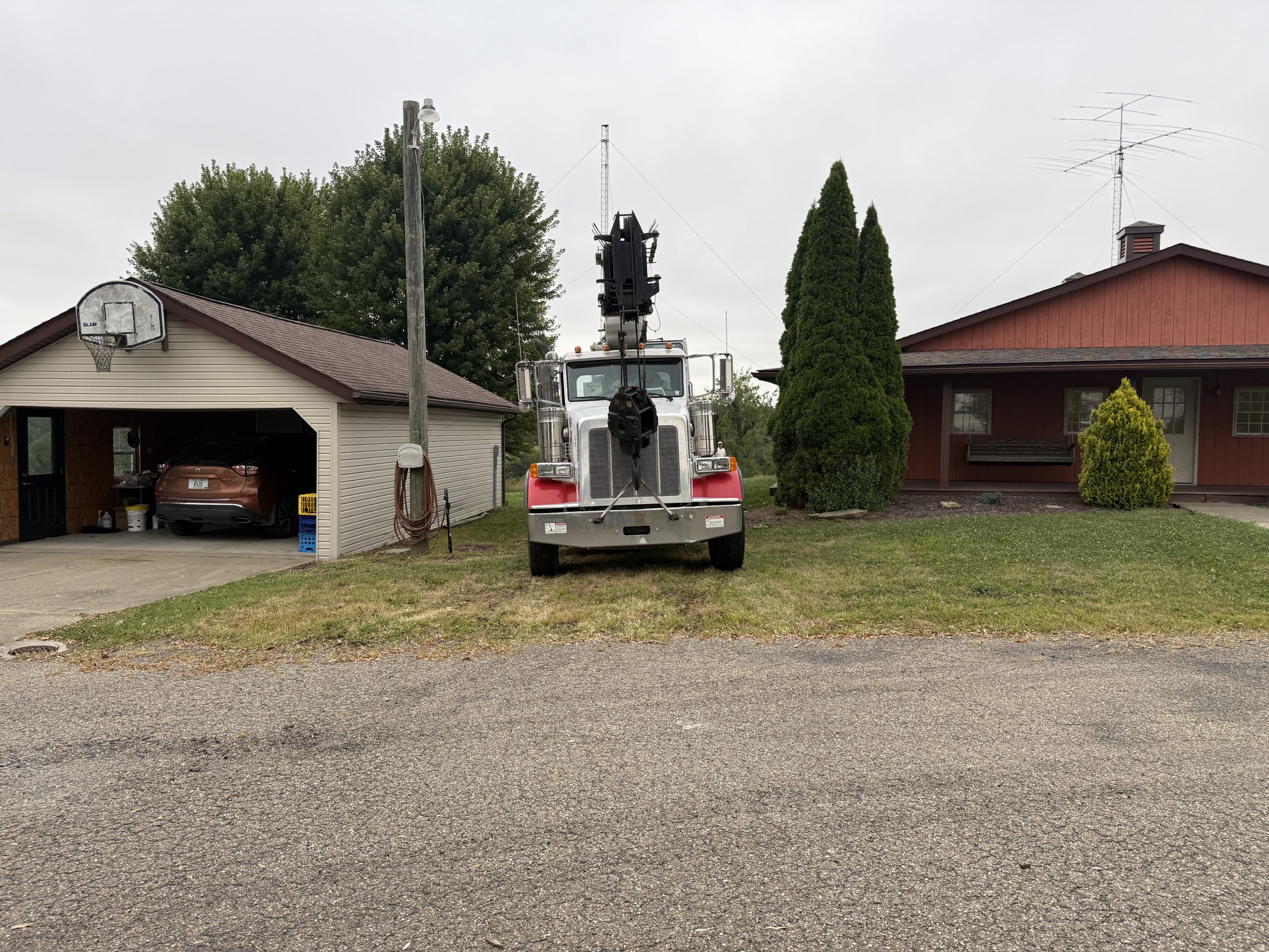
The crane arrived about 8:15am.
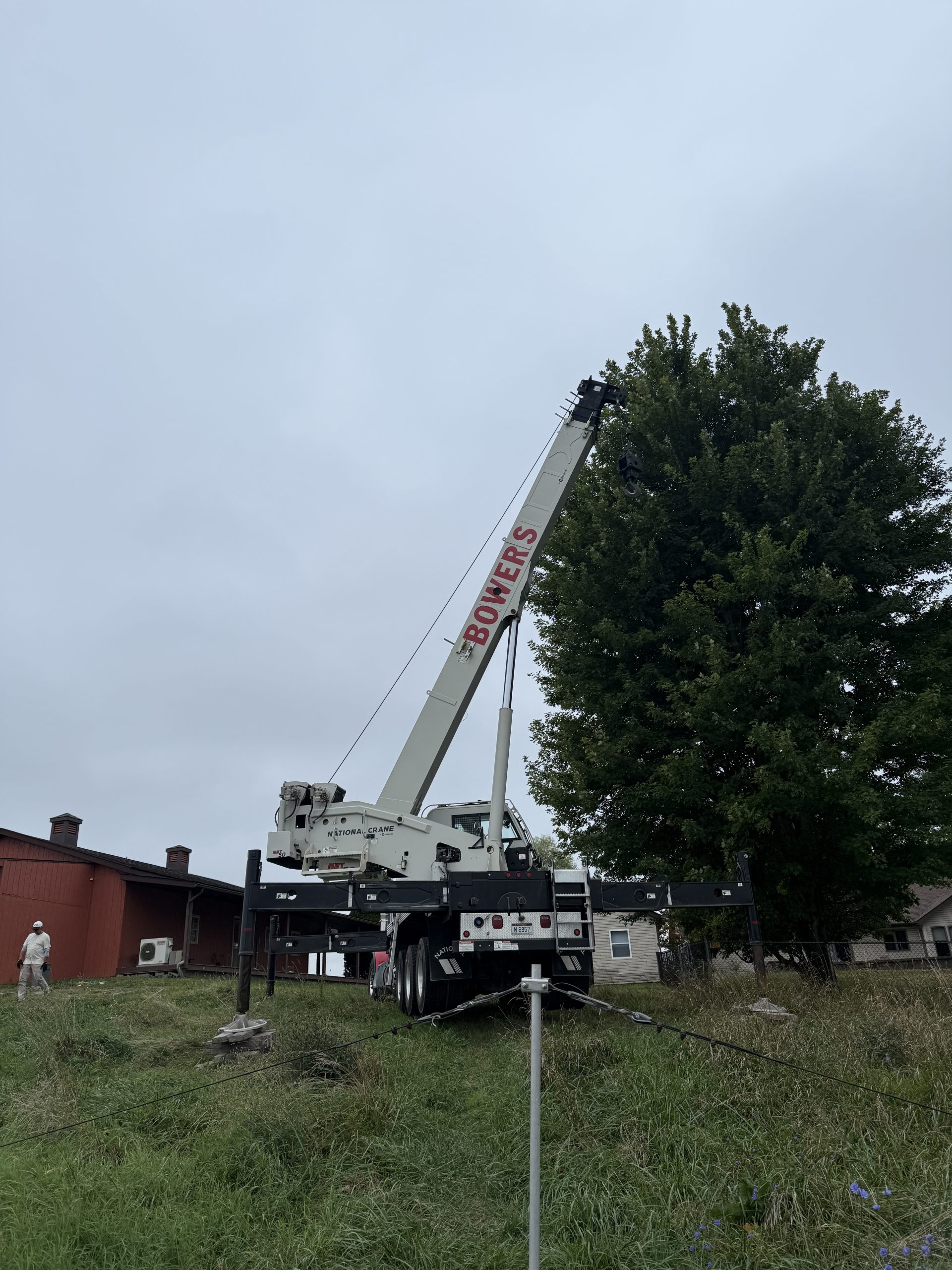
A 55-ton crane was a bit more than I needed, but I couldn’t find anything smaller in the area. It barely fit between the buildings and had to be stabilized to account for the slope.
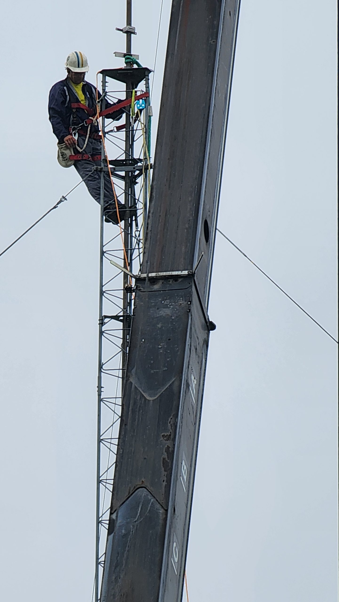
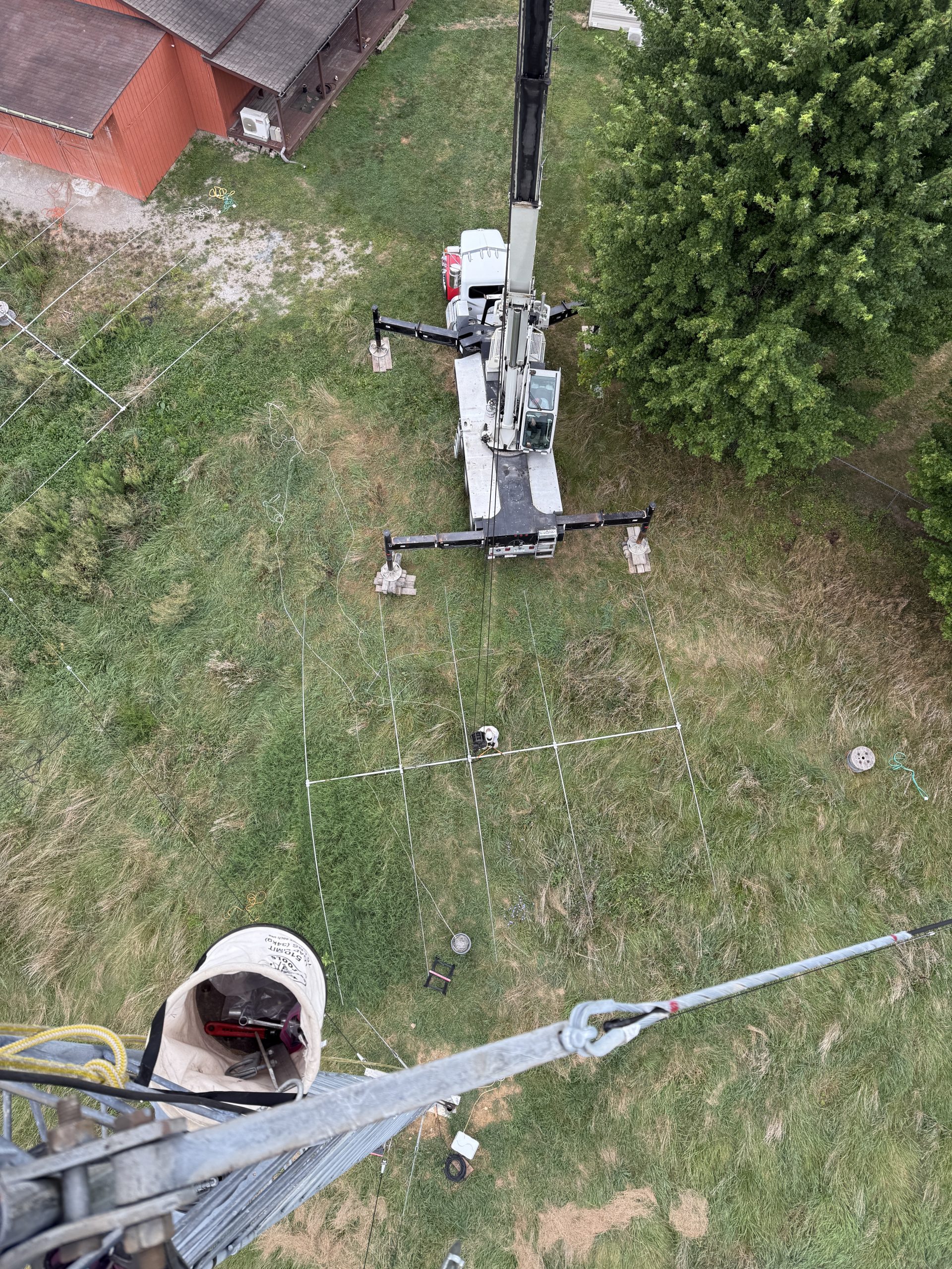
We decided to use cell phones to communicate between the crane operator and me. It worked out really well since I could use earbuds and keep my hands free. Once things were ready, I started climbing. When I got to the to,p I was surprised to turn around and find the mast already halfway up to me!
The 20-foot mast dropped through the thrust bearing, and I put a clamp on it to keep just a few feet sticking out of the top of the tower.
It was time to bring up the Moxon.
Sorry, no pictures from the top of the tower. I was too focused on getting the work done as quickly as possible!
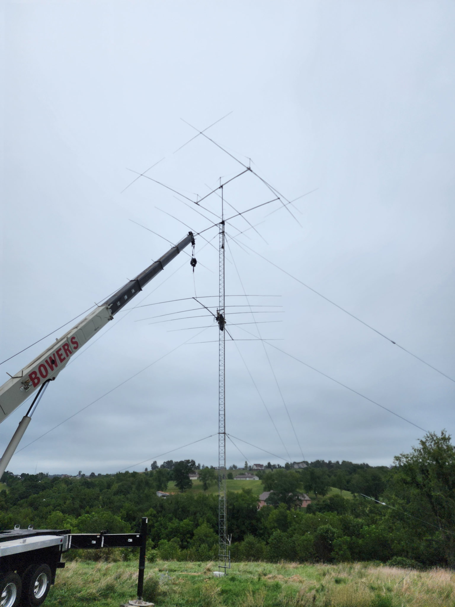
Once the 40 was attached, we used the crane to lift the mast. I dressed the feedline and taped it off as we went. Once it was in the right place, I bolted down the thrust bearing and a second clamp for safety.
It was time to raise the first 5-el 20m.
Time for a quick SWR check. Looking good!
And then the second 5-el 20.
The crane was ready to leave at about 11:45 am. Mission accomplished.
The date for the crane was scheduled for August 21, so the pressure was on to get the 40 and 20-meter antennas assembled.
I purchased a 40-meter 2-element Moxon from W3YQ. I have always wanted one of these. The antenna was originally built by N8AA and it was a work of art. Everything was done properly. Because Tim was able to deliver it to me on his 20′ trailer, I didn’t have to do much more than assemble the pieces.
August 6, 2025
I started with the sidemount attached to the tower. Then assembled the boom and added the elements.
What makes a Moxon complicated and unwieldy is the crosspieces on the elements.
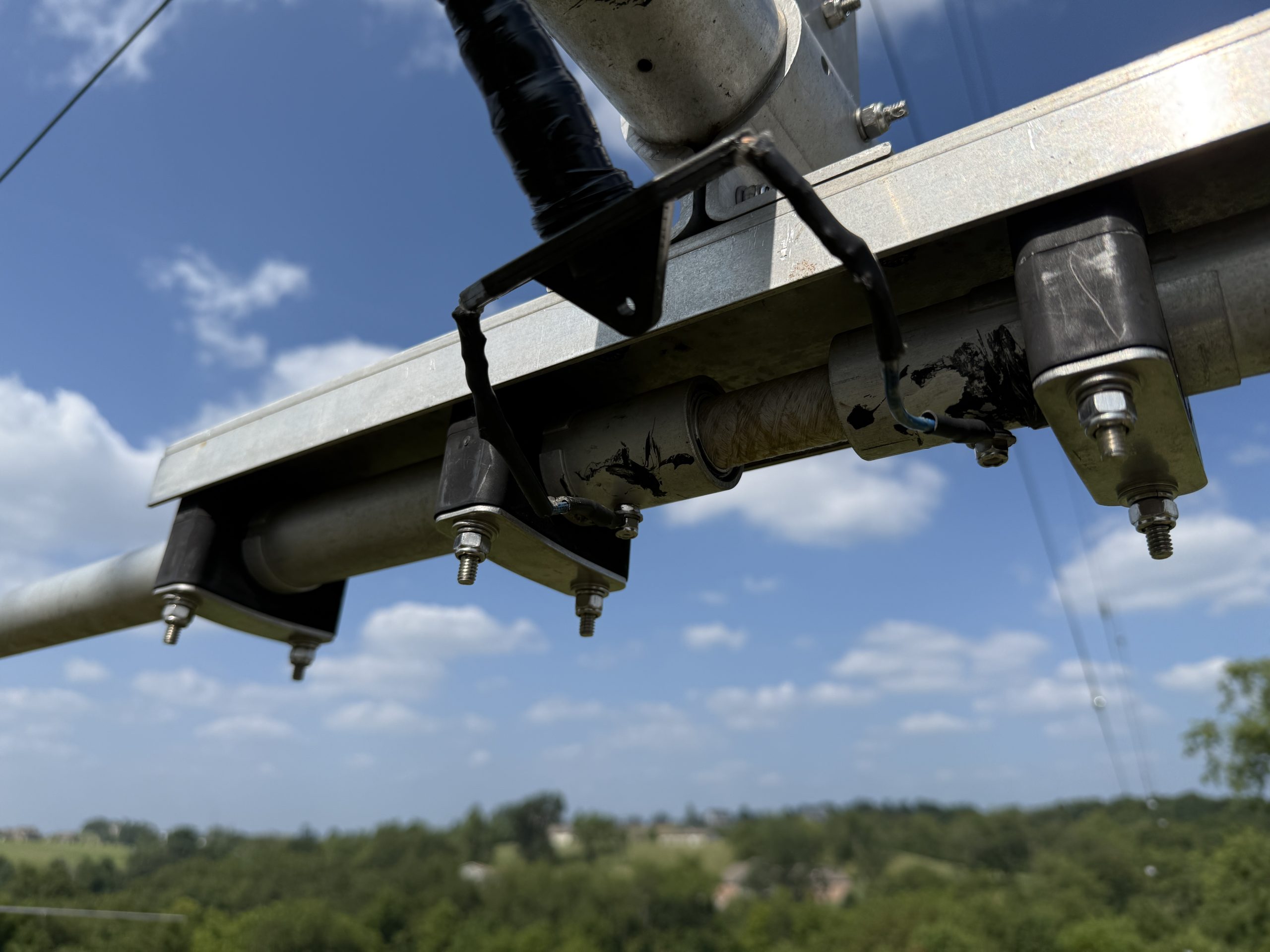
For the feedpoint, I used a DX Engineering choke placed inside a piece of PVC pipe with shrink wrap covering everything. The PVC provided some structural integrity, so I could elevate the choke from the boom and use hose clamps to tighten it all down. This was all left over from my 40m stack in MA.
The antenna is nearly 100 pounds and is almost more than I could lift. I pulled it up a few feet and took an SWR reading. It had a curve that looked ok, but was below the band. Good enough to confirm everything was connected.
August 10, 2025
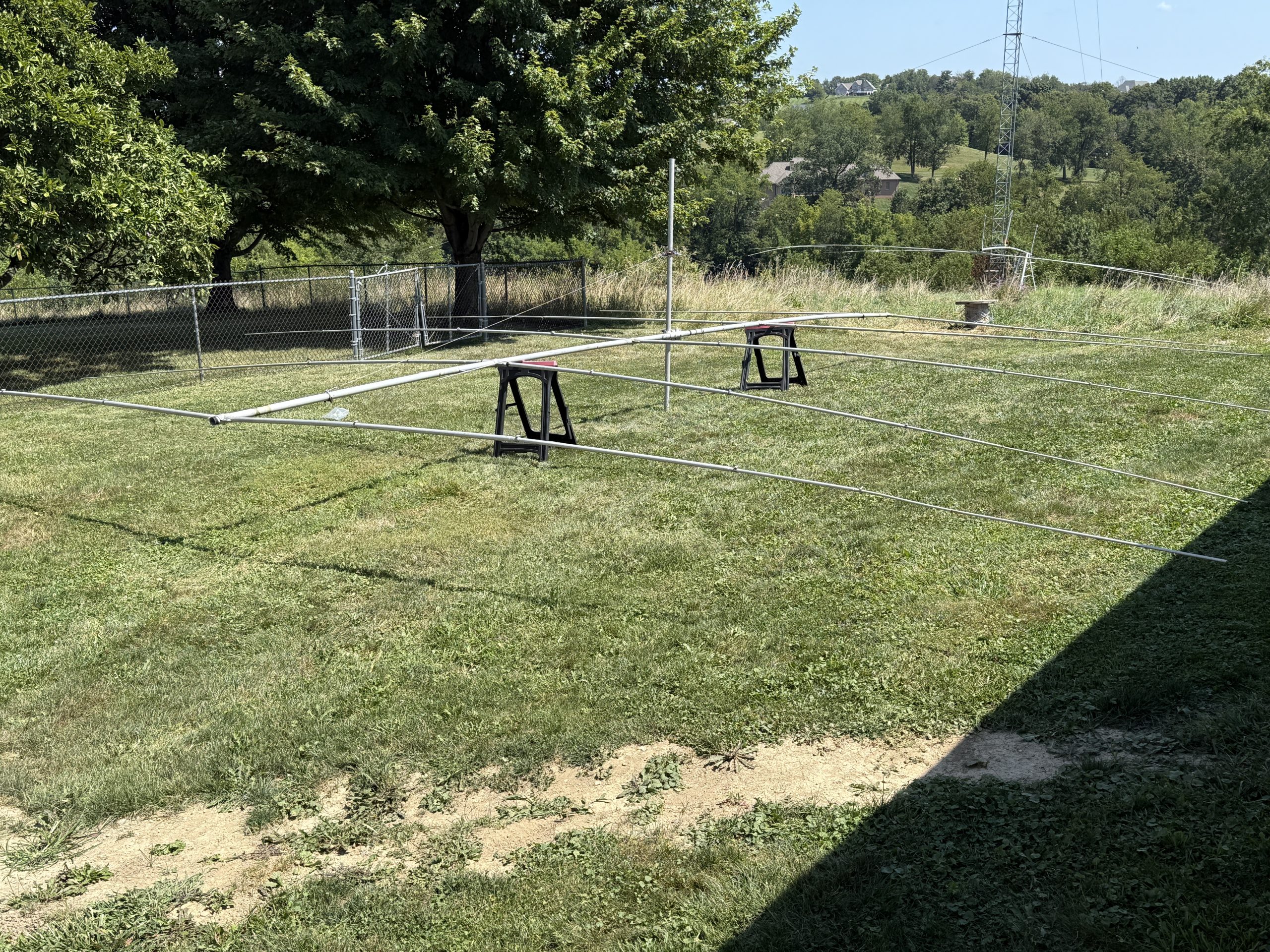
With the 40 done, it was time to turn attention to rebuilding two Hygain 205-CA antennas for 20 meters. I had just enough room to do this in the yard.
These antennas had been up for more than 30 years in MA. One had lived through a severe ice storm. I was surprised to find the boom-to-element clamps had bent (warped) on some elements. When I put the antenna together, I could have elements that were drooping or looked like raised wings. Thank goodness for standardization. I found some undamaged Hygain clamps on one of the TH7DXX that were in the barn. This helped me get both antennas looking a bit more normal. I regret that I didn’t take more pictures to show how the clamps warped.
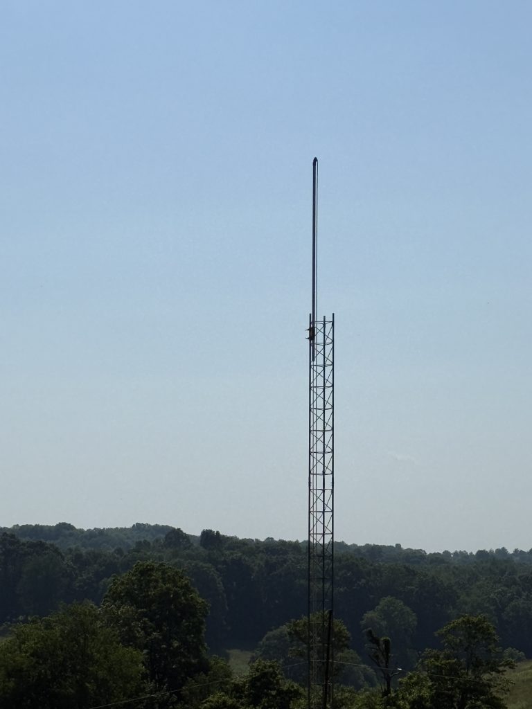
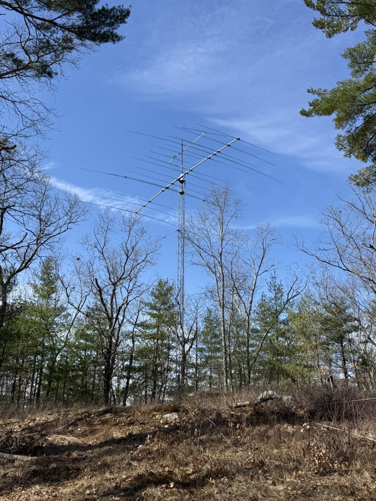
I was anxious to get some antennas on the new tower. The plan was to have a steel mast with 10′ out of the top of the tower holding a Cushcraft A3-S WARC band antenna and a Force 12 C31xr tribander for 10, 15, and 20.
July 14, 2025
I attached a sidemount about 5′ up on the tower and put a mast inside of it. This gave me a place to reassemble the C31xr.
July 26, 2025
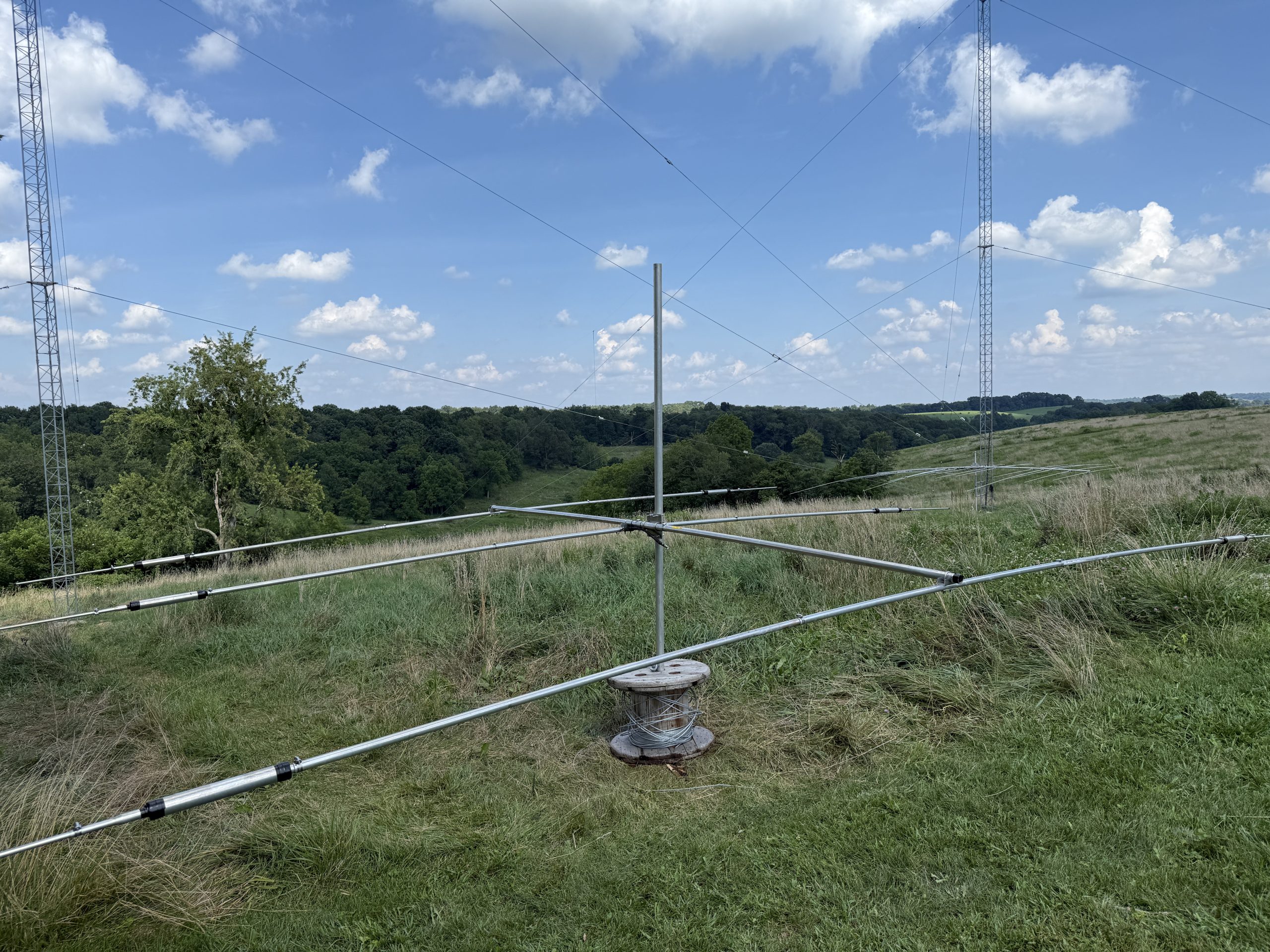
Because it was much smaller, it was easy to assemble the WARC antenna using a pipe inserted into a cable reel.
August 1, 2026
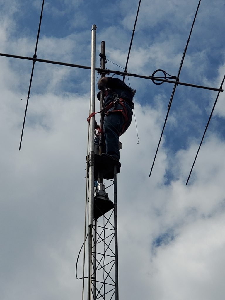
It was finally antenna-raising day! Mike was on the ground, and I was on the tower.
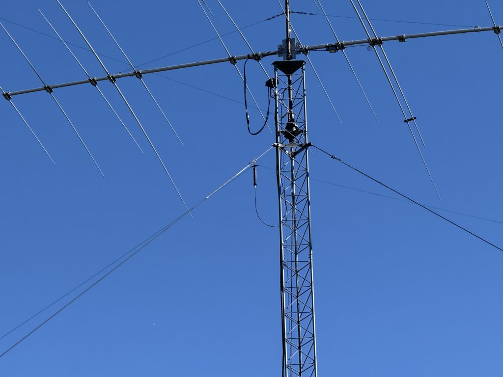
The Cushcraft antenna was first. It was easy to corkscrew through the guy wires and attach to the mast.
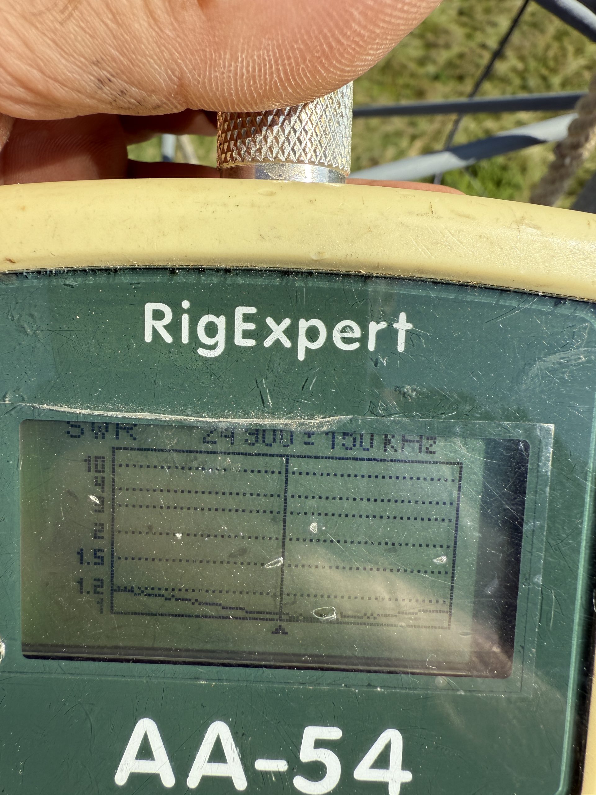
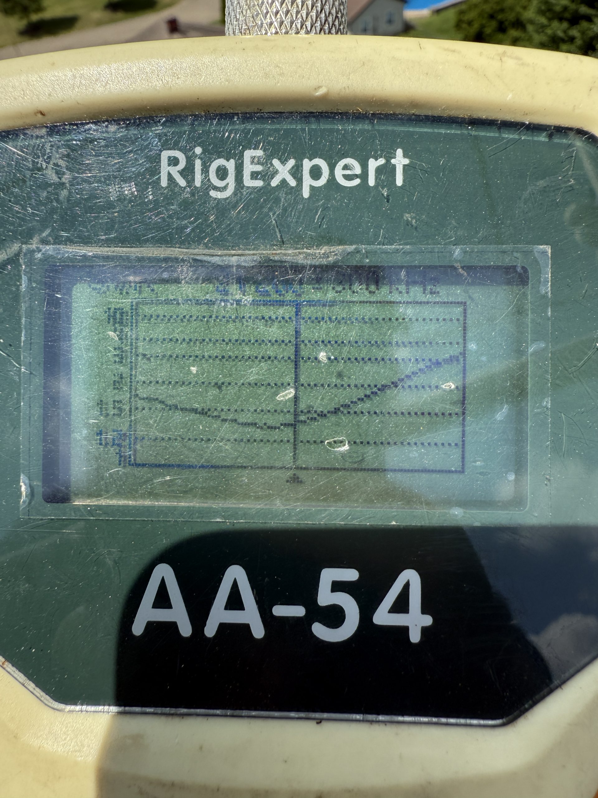
The AA-54 antenna analyzer was next. Very happy to see these SWR curves!
I bolted the C31xr’s heavy-duty boom-to-mast clamp to the mast before I came down.
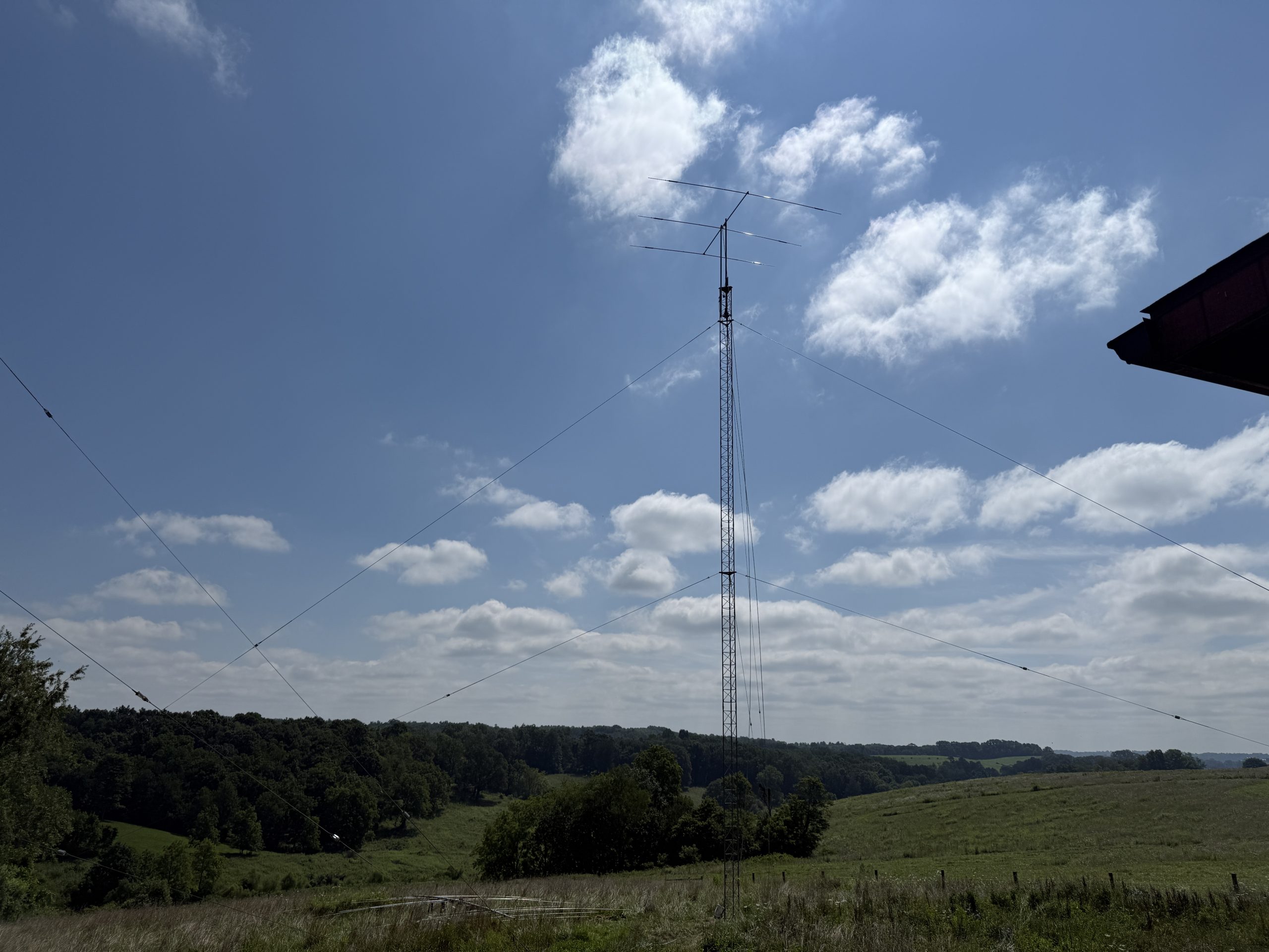
It was exciting to have one antenna up. But it looks a bit lonely.
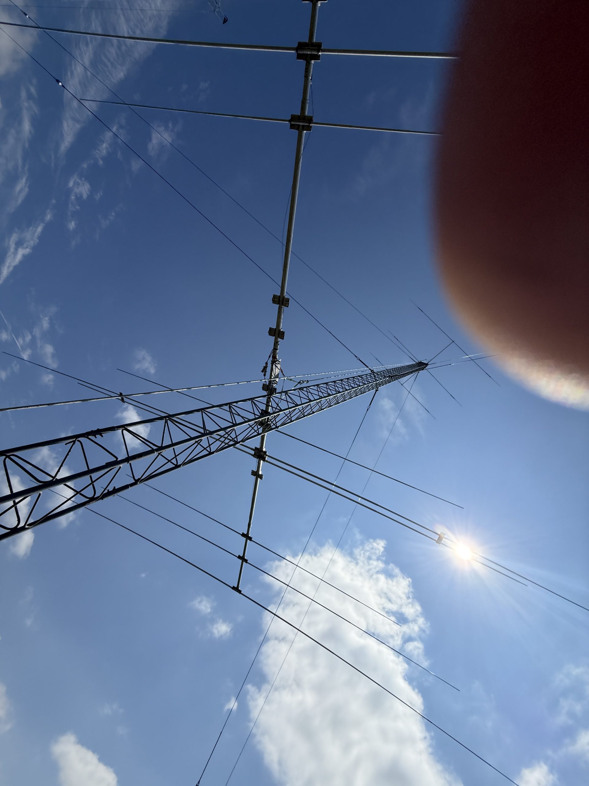
The C31 is a big and heavy antenna. There is no way Mike and I could have lifted it without the Capstan wench. It has a lot of elements that make it difficult to maneuver. We removed the elements that could be reached from the tower to make more space. With some effort, I climbed the tower as the antenna was lifted. I was able to work it around the two sets of guys.
There was only this one photo (with a thumb) since we were both fully engaged in the process! It does show the removed elements.
Once the antenna was bolted to the mast, we brought up the removed elements and mounted them to the boom. The Force 12 has a very clever way of doing the boom-to-element clamps that made this process relatively easy.
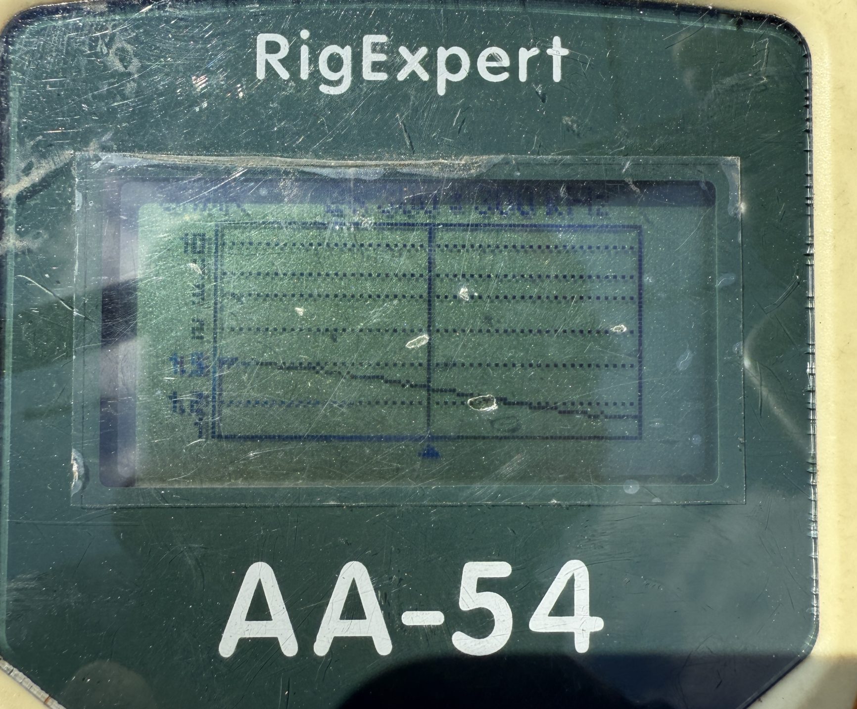
The SWR curves were not as great as I had hoped. The C31 has known issues on 15 meters, and I expect adjustment of the loading coil will make it better.
Curves for 20, 15, and 10:
By 1 p.m., the project was complete, and it was time to pack up and find some lunch.
I should have checked the SWR on the A3S after the C31xr was up. The C31 has a resonance on 17m that caused some interaction with the A3S. SWR on 12 and 17m was still OK, but not as good as it was when the antenna was by itself. A future project will be to turn them 90 degrees and see if that resolves the issue.
One more picture of the day’s work.
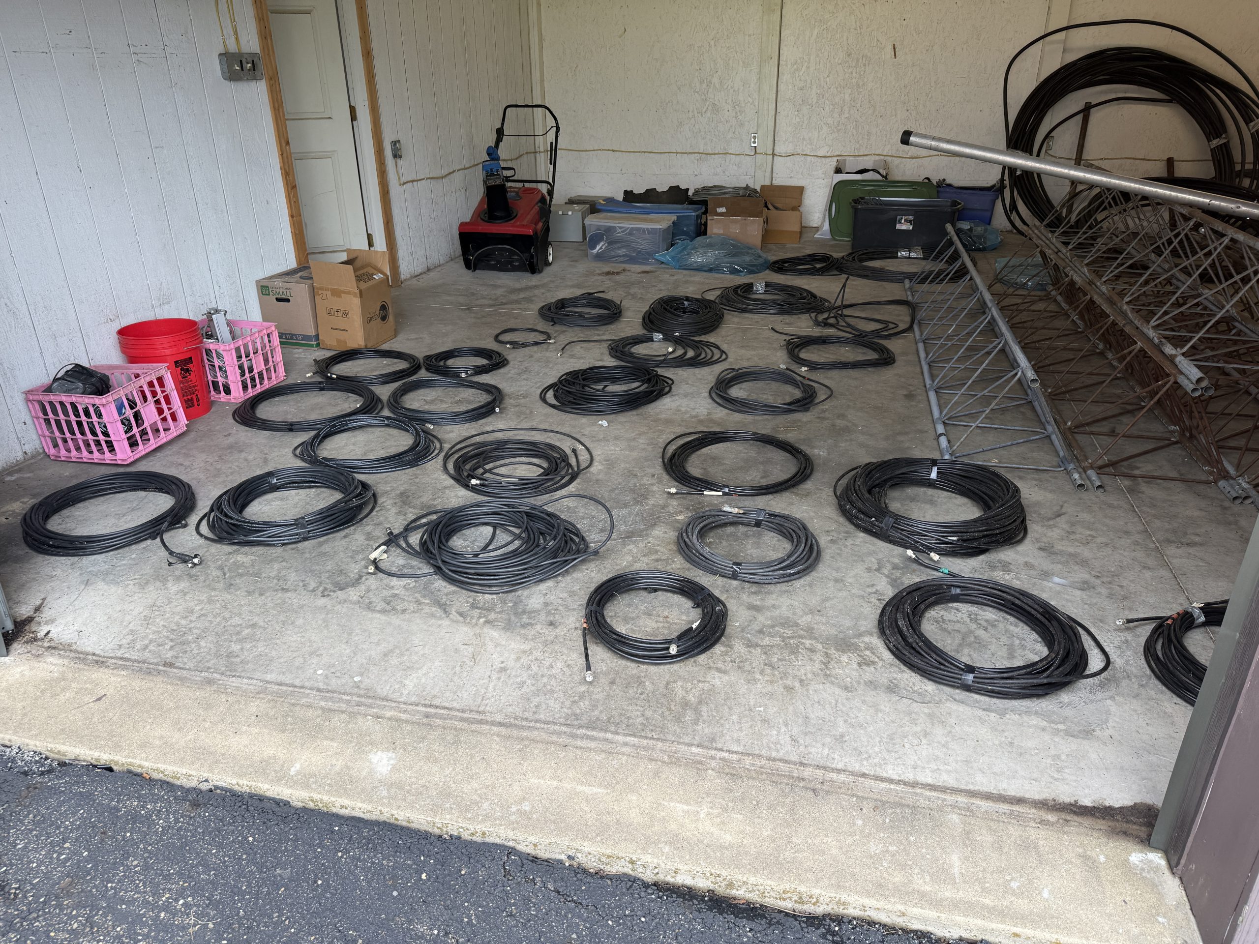
The next project was finding feedlines and control cables.
With the towers up, it was time to work on grounding. Two books influenced my thinking and actions on this topic.
Grounding and Bonding for the Radio Amateur, Ward Silver, N0AX. Published by ARRL
Lightning Protection – A Comprehensive Guide for Amateur Radio, Ron Block, NR2B. Available at https://www.wrblock.com/book
Both are excellent and recommended reading for anyone with a station in a lightning-prone area (like Ohio).
July 21, 2026
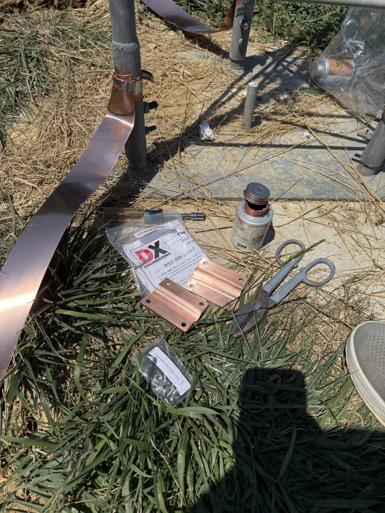
I decided to use one ground rod for each leg of the tower, with a copper strap circling the tower to connect everything.
Driving the ground rods was easy in the rich topsoil. I had to stand on a ladder and use a sledgehammer to get them started.
For the south tower, I tried just making a slit in the earth and pushing the strap into it.
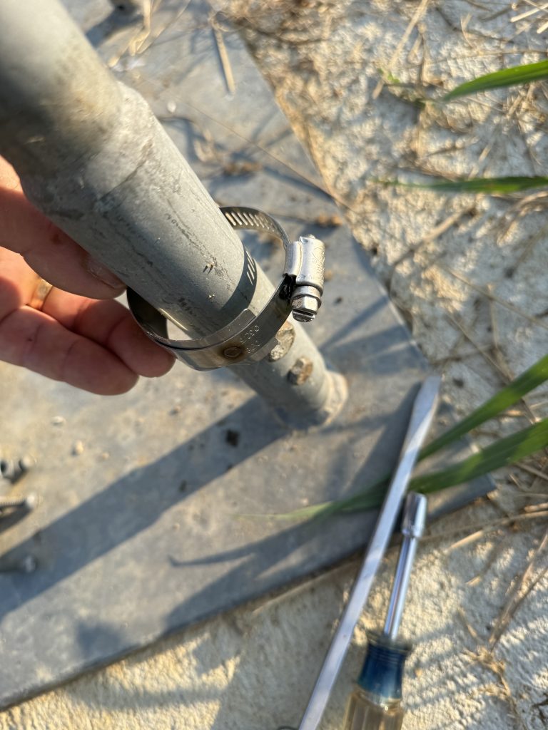
I used clamps from DX Engineering to connect the copper strap to the tower legs. The clamps are simply hose clamps with a piece of stainless steel welded to them. The intent is to reduce corrosion due to dissimilar metals at the connection. I used plenty of SS-30 between every connection.
The clamps that connect the strap to the ground rods are a piece of art when you take them out of the package. They made the connection easy and very solid. The strap going all the way around is bonded to the strap coming from each leg at the ground rod.
August 3, 2026
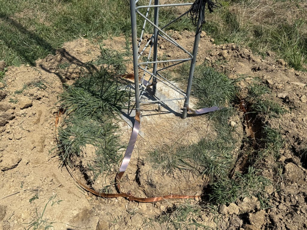
For the north tower, I dug a trench around the tower. It was too hard to push the copper strap into the dirt. The trench was the way to go.
I filled in the trench and covered the ground rods. And with that, several hundred dollars of copper disappeared waiting for their chance to conduct (or prevent) a lightning strike.
I had no trouble putting up the first 10′ of tower and stringing the temporary guy wires. The challenge was going to be finding some helpers to work on the ground, doing the hard work of waiting and pulling.
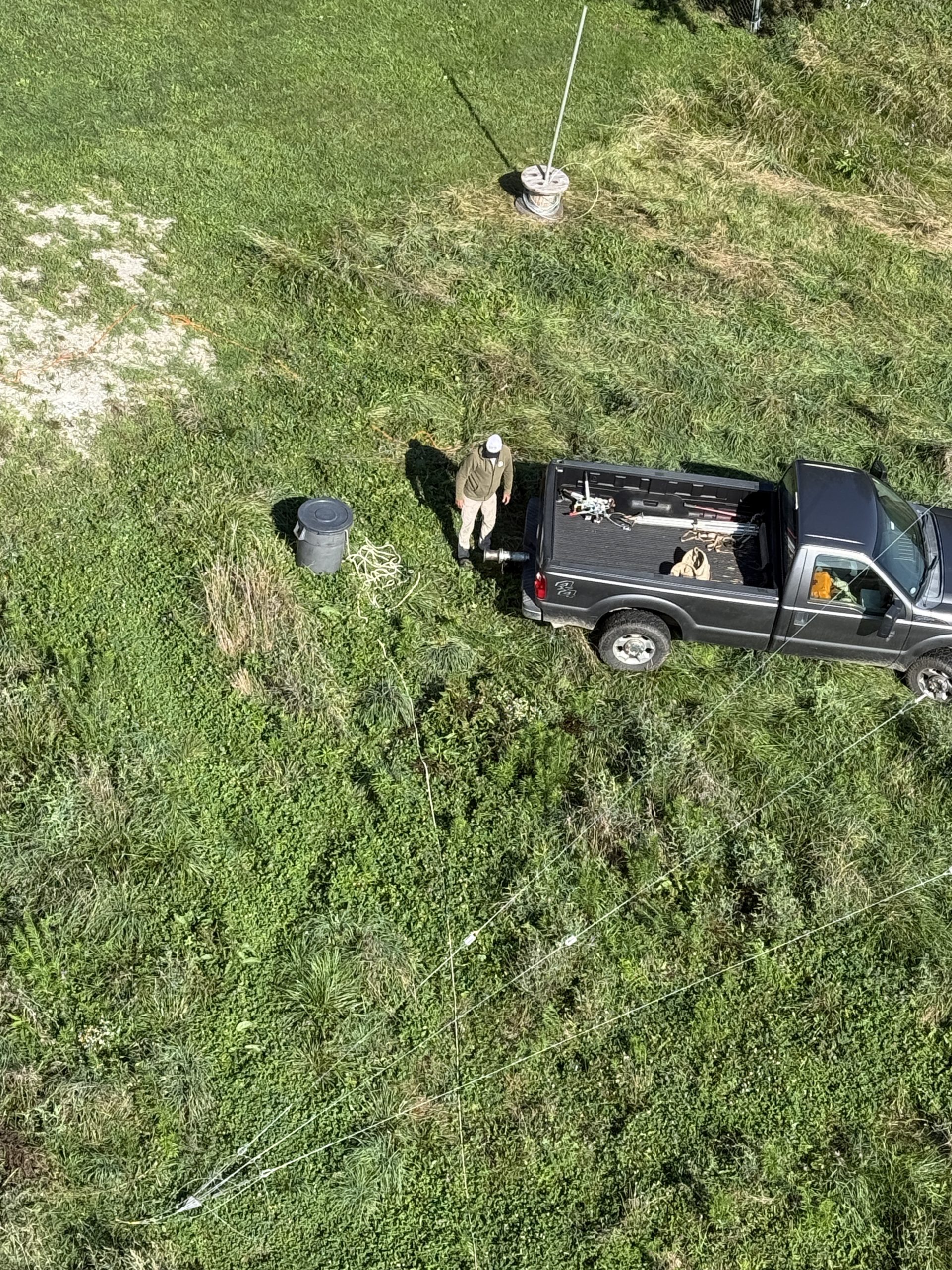
On one of the Q5 Contest Crew episodes, I was reporting on the station building progress and mentioned that I needed to find some ground crew. I was pleasantly surprised when several people contacted me to offer their help. The big break happened the week before Field Day when I was introduced to Mike WA3C via Contest Crew fan Tom KF8AVC. Mike has a multi-tower station of his own, considerable tower experience, and lives just 45 minutes away. He very generously offered to come over and help.
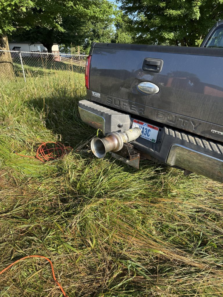
In addition to his experience and time, he also brought the tool that made everything possible. A Capstan winch that could bolt to his truck. This winch enabled us to do the work with just the two of us.
Capstan winch
July 1, 2025
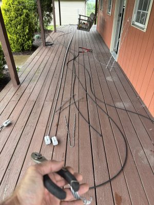
I know I have all the parts to build the station – I just have to find them and then modify things to fit the new situation. Today was guy wire day. I unrolled the Phillystran to know what I had and then started reworking the steel guy wires and insulators.
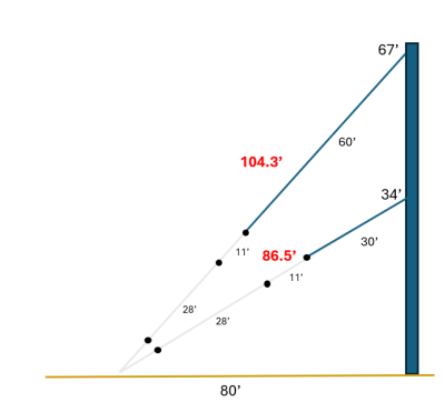
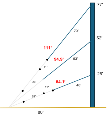
I chose guy wire lengths based on an NCJ article by N2IC. His analysis recommended lengths of less than 11′ or very narrow guy-wire windows at approximately 28 and 41 feet. I wanted Phillystran down to about the 30′ level, then an 11′ section, and then 28′ sections as needed.
July 7, 2025
Mike arrived for our first session about 8 am on a morning that was boiling, humid, and calm. You could see the moisture in the pasture, and it was stifling as the sun warmed the air and pulled humidity up from the grass.
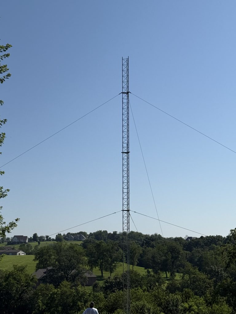
We started with the South tower. It was to be 70′ with guy wires at 34′ and 68′. It was a smooth process to rig the gin pole, pull up a section, bolt it on, and then repeat. We were ready for the first guy set after only 90 minutes of work.
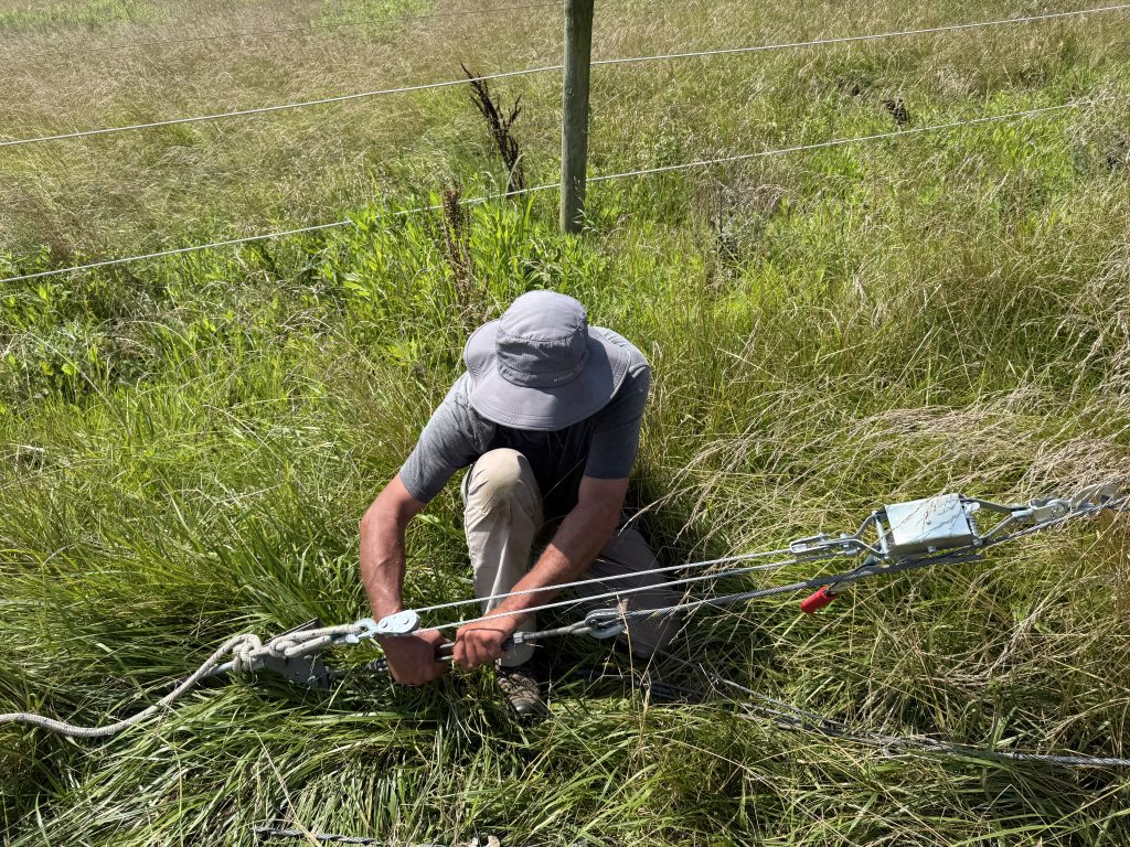
Mike introduced me to a clever way of installing the guy wires. He had three come-alongs so we could get each line tensioned before attaching it to the turnbuckle. (I had always done it by moving from guy anchor to anchor, tensioning each until everything was straight.)
Mike WA3C installing a guy wire
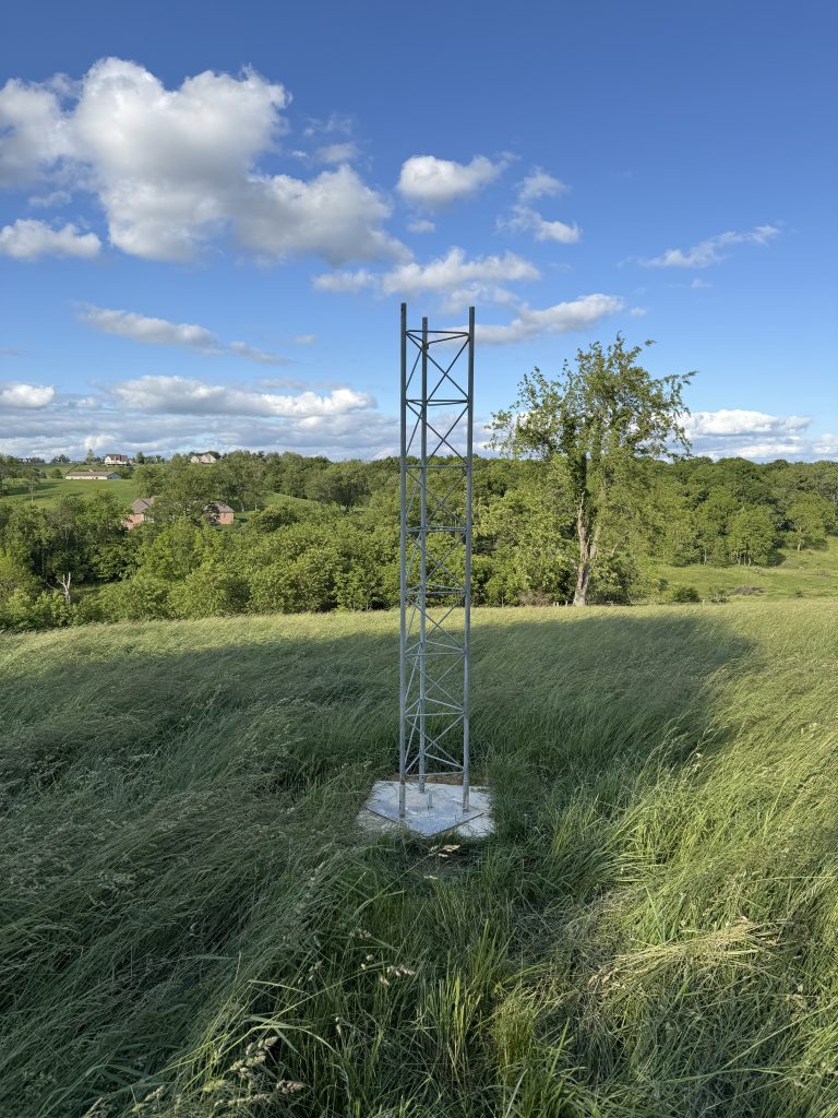
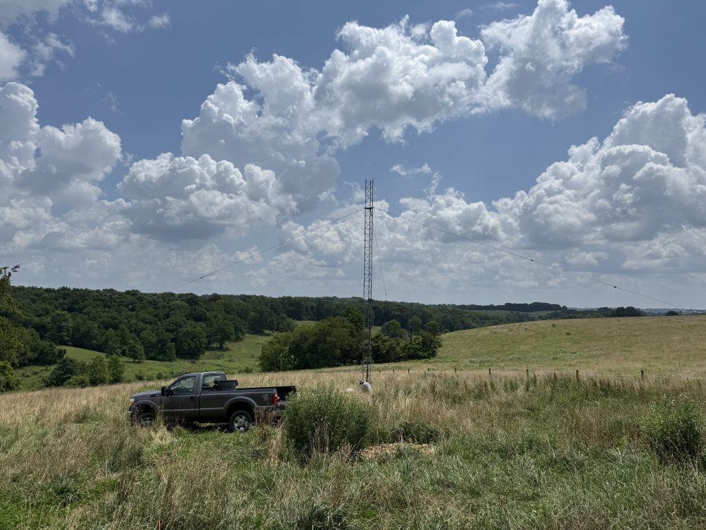
It was great to step back and see some progress.
It was now almost 1 pm, and the heat was wearing on us. I normally do well with heat, but it was oppressive when working at ground level on the guy attachments. I decided I had had enough, and we called it a day.
July 10, 2025
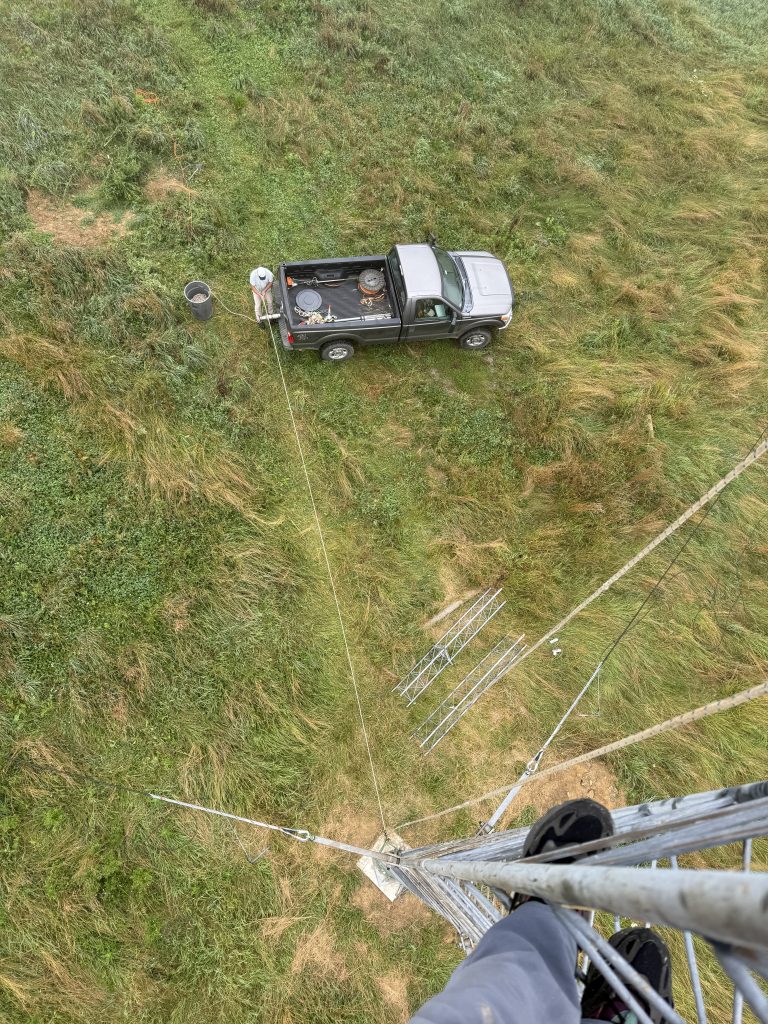
We were back at it on a still warm and humid, but more cloudy morning a few days later. With just two of us, there aren’t many photos of the work in progress. I did grab this one as Mike was wrapping the rope on the winch to pull up a section.
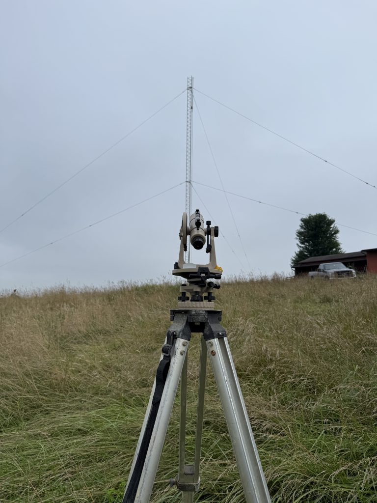
By 11:15 am, we had all the sections up and the second set of guy wires attached. Mike brought his Loos tension gauge so we could check the tensions. He also brought his transit. The result was a tower that felt very solid and was truly vertical!
We added the top plate and called it a day at around 1 pm. I was thrilled to have this tower fully up in just two mornings of work.
July 14, 2026
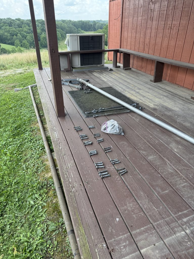
It was more work than expected to repurpose the guy wires from W1 and configure them for the new towers. I think I spent several days working on this.
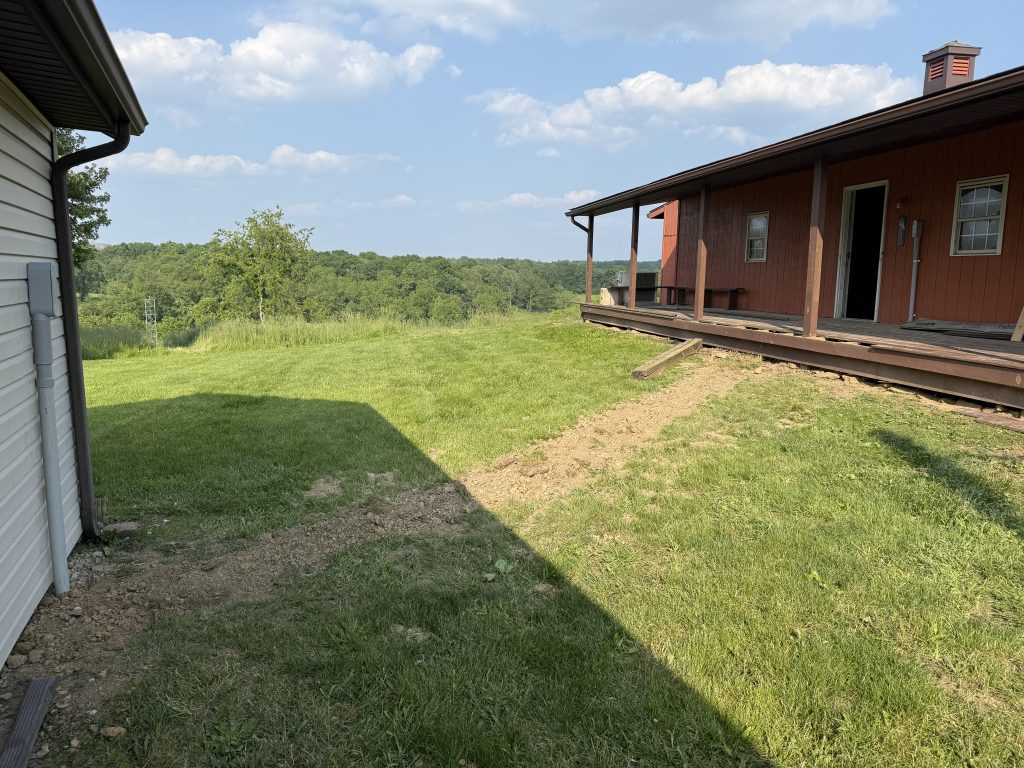
It was nice to have a covered deck to work under!
July 16, 2025
The heat and humidity finally broke, and we had a beautiful day to start work on the North tower. This one was to be 80′ with guy wires at 39′ and 78′.
We were getting pretty good at this and had the tower with the first set of guys up by 1 pm.
This tower will feature a 2-element 40m Moxon and a 5-element 20m Yagi antenna. Even with just two sections above the first guy point, I could feel things were wobbly. After a bit of thinking, it just seemed like it would be a risk to try to do this with only 2 guy sets. I had everything I needed to add another set, so I decided to rework things to have 3 guys at 25′, 52′, and 78′.
July 22, 2025
I was able to install the guy bracket at 50′ and loosely attach the guy set.
July 23, 2025
Mike arrived around 8 am, and I explained the change of plans for guying. I installed a guy bracket at 25′. We tightened the new set at 50′. That enabled me to remove the set at 35′ and move it down to the new bracket.
The bracket at 35′ could now move up to 78′ after two more sections were added. By 12:30 p.m., we had the tower fully up and guyed.
I had the C31xr assembled at the base of the other tower, and a Cushcraft A3WS 12/17m antenna was also ready to go. Given the power of the Capstan winch, I asked Mike if he was game to try raising the antennas to the top of the south tower. He agreed, and we set a date.
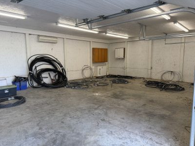
The building chosen for the shack only had 120V service served by a single 20A breaker. I wanted 220V service to power the amplifiers. The closest access to 220V came from the nearby barn building, which had a 100A service panel.
A local contractor advertised on Facebook that his electrician was finishing a job and had a few days available. I contacted him, and they were able to start within a few days.
To keep costs down, I had them focus on installing a new panel in the shack and getting power to it from the barn.
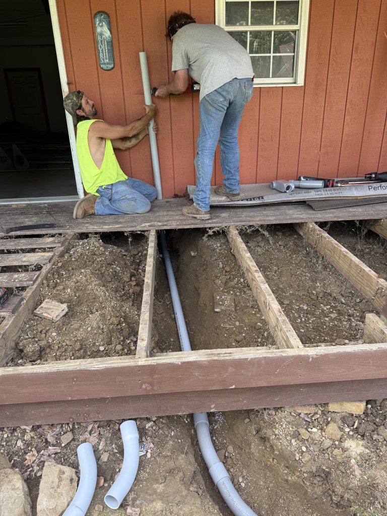
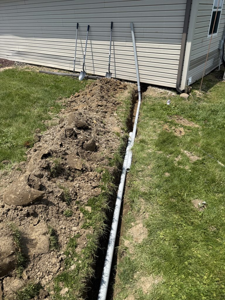
The complexity in getting power out of the barn and over to the garage. This involved digging a trench, running conduit under a porch, and punching through the walls of each building.
They made good progress and had most of the work done within a day.
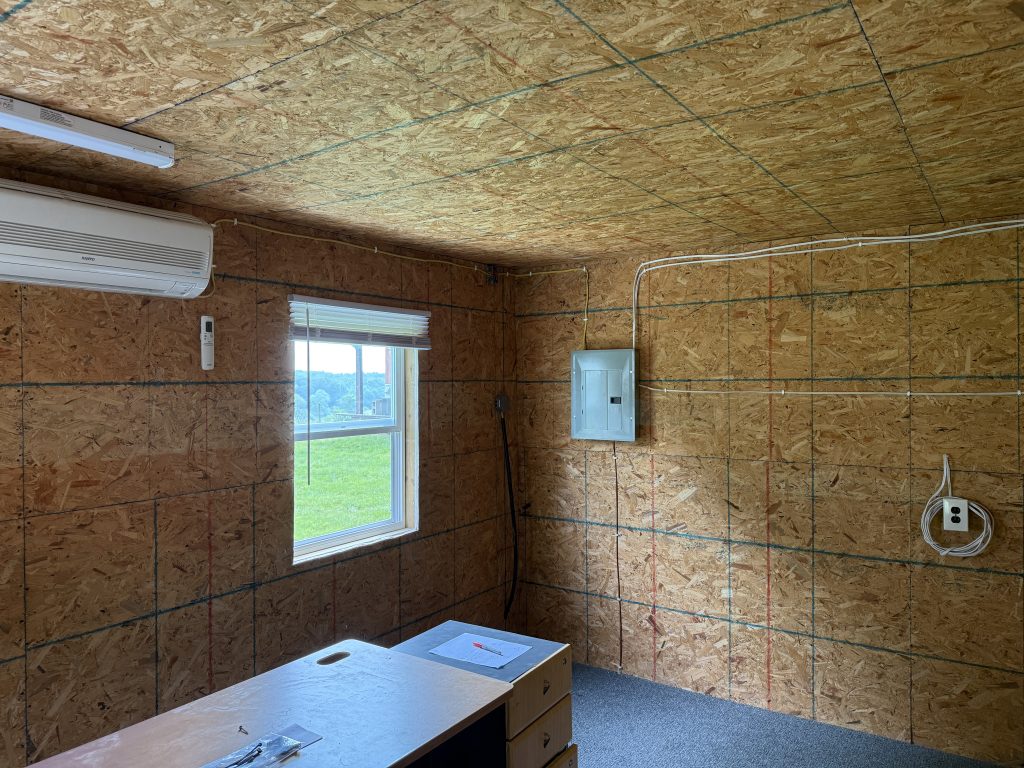
The barn side has a 60A breaker feeding the run to the barn. The shack has a small electrical panel with two 220V circuits (20A each), multiple circuits for the shack and garage, and room for expansion. They also added ground rods and grounding for the shack panel. The existing 120V circuit coming from the house was capped off and will not be used.
Completed electrical panel
Once that was done, I was able to do the shack wiring myself. Even though the electricians weren’t keen on surface wiring (they would have preferred putting everything in conduit), I kind of liked saving money and retaining the ability to easily make changes later if needed.
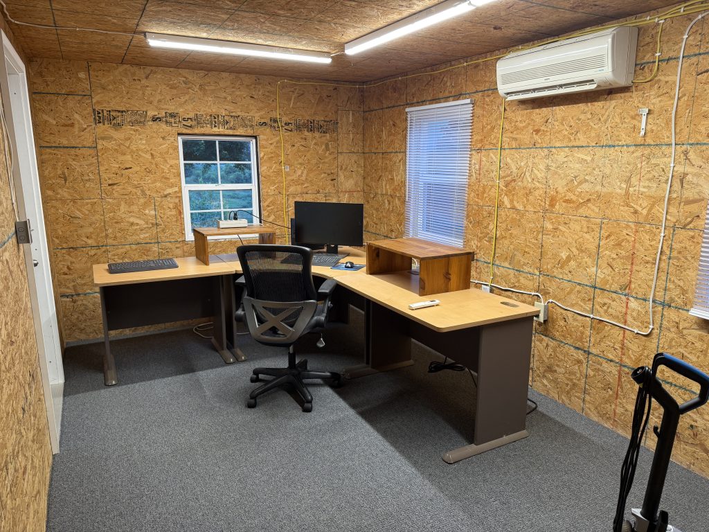
I chose LED lighting fixtures that let me adjust the brightness and color warmth, as I wasn’t sure what the room would need. Might still be some room for improvement in this area once I start spending long operating sessions in contests.
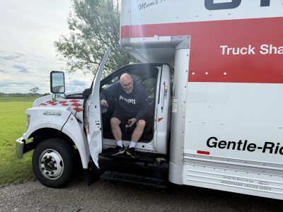
The new location is on the way to the Dayton Hamvention, so that offered a great opportunity to combine moving with some fun. Mark KW1X agreed to make the trip with me and his help with loading, driving, and unloading was invaluable!
Monday May 12
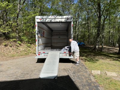
We picked up a 26′ U-Haul truck at about 9 am. This thing was huge! I had followed the advice of my neighbor, who suggested it was always better to have too much room than not enough. This proved to be good advice!
Mark KW1X checking out the empty truck
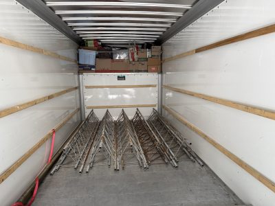
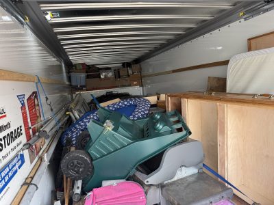
We loaded as many boxes as possible into the attic area above the cab and then proceeded to the tower sections. Five sections fit perfectly across. And Rohn 25 sections fit neatly inside Rohn 45. One nice thing about the big truck is that it had a 20′ bed so the longest steel mast could sit directly on the floor.
From here on, it was just a matter of carrying things and finding a place for them to land.
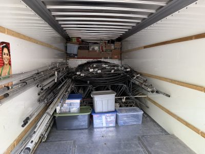
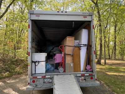
Once all the towers, antennas, and feedlines were onboard, we filled the remainder with household items and furniture. It took from 9:30 am to around 4 pm to get everything in.
We still had some space, but I didn’t want to just run around the house throwing things in at the last minute. Plus, we had had enough of being movers…
Tuesday May 13
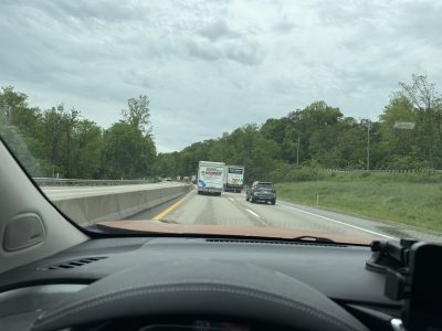
After a good night’s sleep, Mark was back at 6 am, and we headed out. It is 625 miles from Uxbridge, MA to Belmont, OH. We passed through 6 states and only had to stop at one weigh station. Mark volunteered to drive the truck, and I had the luxury of driving my car.
The weather was good most of the way, and it was just a matter of working around the number of large trucks that fill the major east-west Interstates. We stopped for lunch and gas breaks. We arrived in the late afternoon around 5:30 pm. Mark was glad to get out of the truck!
We were too tired to do any unloading and headed out to a local diner for dinner.
Wednesday March 14
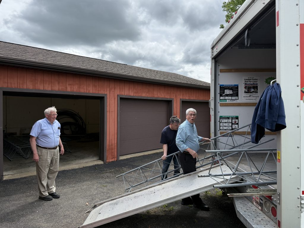
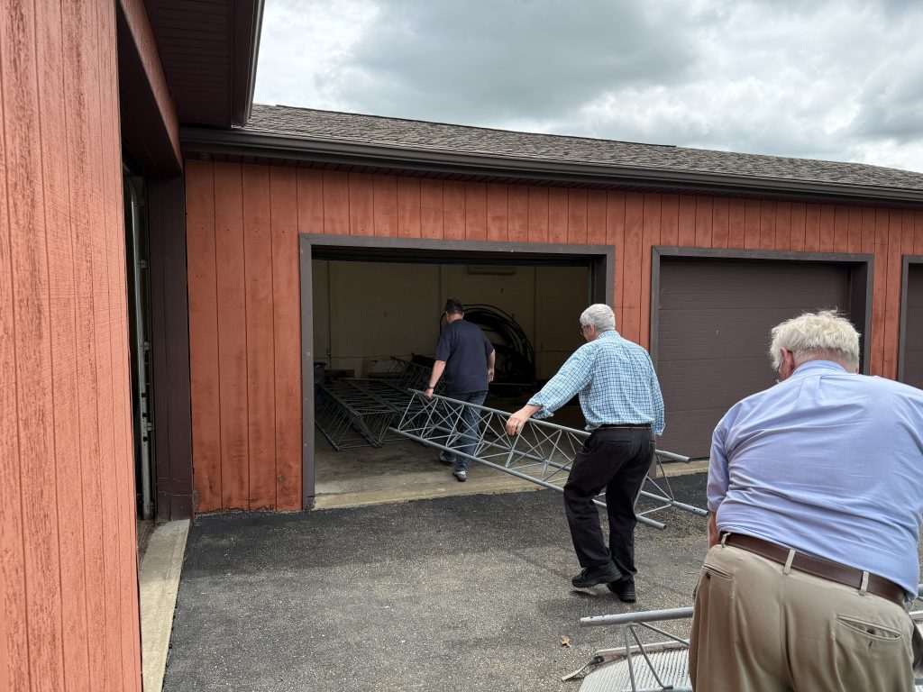
No fun to open the truck door and see all the stuff we had to carry and find a place for. Fortunately, unloading is always faster than loading.
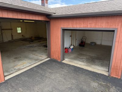
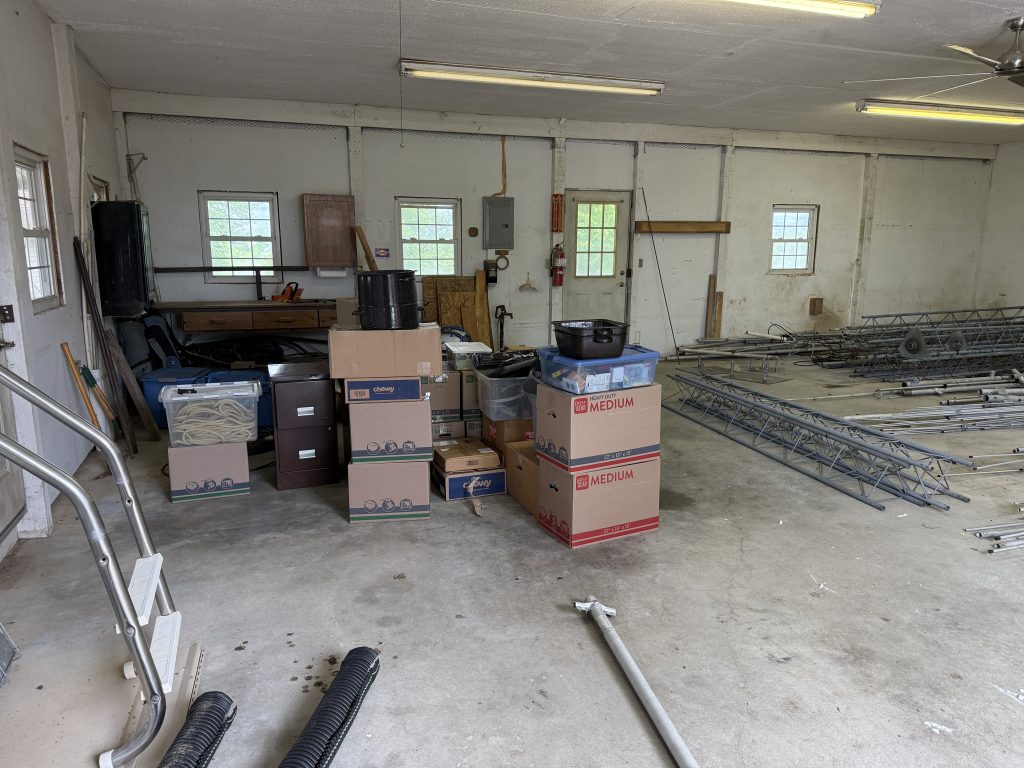
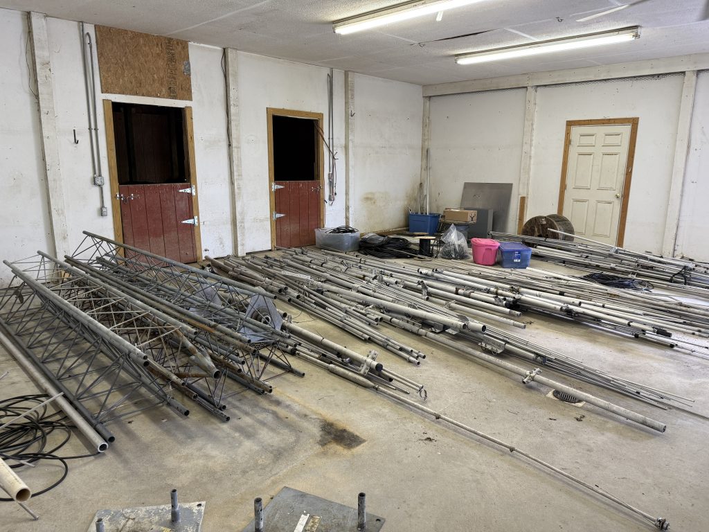
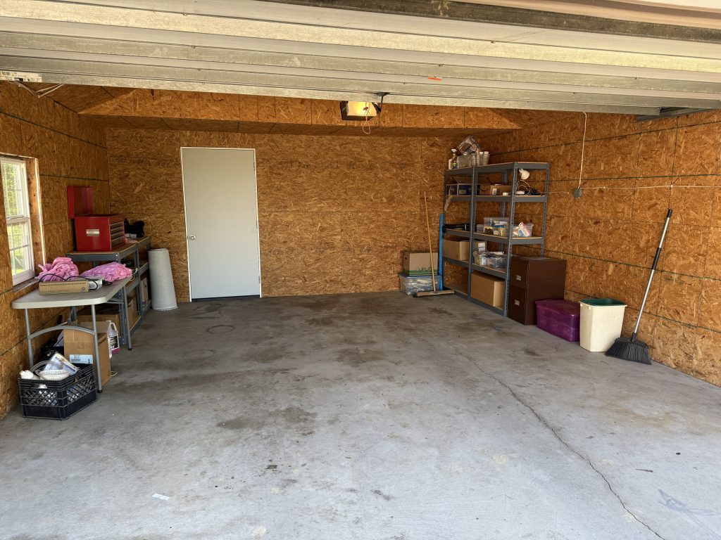
We also had a convenient building to unload all the radio stuff into.
When I first looked at this house, I remember wondering what I would ever do with all of this garage space! What a silly thought.
Around 11 am, just as Mark and I were getting tired and looking at a large pile of tower sections and aluminum that needed to be moved, we had some visitors. Martin AA1ON was driving from Boston to Dayton and had two passengers riding along with him – Fred K1VR and Zoli HA1AG. They arrived at the perfect time, and we put them to work.
In an hour, we had made great progress.
We all went back to the local diner for lunch, and our visiting workers continued their trip to Dayton.
We spent the afternoon cleaning out and returning the truck. And moving some furniture and unpacking things inside.
Thursday May 14
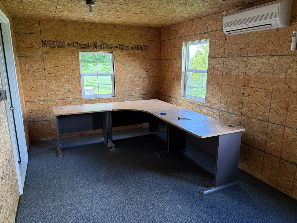
I spent the morning assembling the desks in the new radio room and unpacking some of the radio paraphernalia.
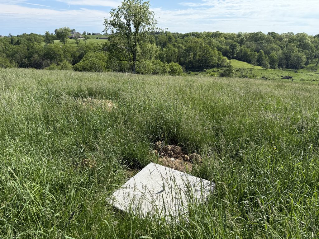
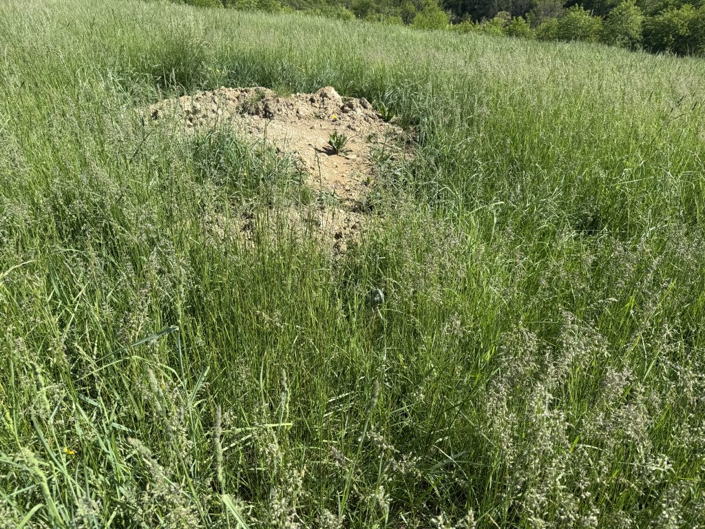
It was amazing how much the grass had grown in the 4 weeks since the concrete work was done. What used to be a clear field was now 3′ high grass that was hard to walk through and hid all the guy anchors from view.
We headed out on our 3-hour drive to Xenia around noon.
The Hamvention was its usual blur of conversations, meetings, forums, flea market walks, and late nights.
Sunday May 18
Mark needed to get home on Monday. We decided there was no reason to detour back by the house. So it was a straight 800+ mile drive back to MA. We both agreed we had had enough driving for one week. I slept most of the first 18 hours I was back home!
It was kind of hard to believe that I would be back in the car 5 days later, driving out to K3LR for the WPX CW contest.
I returned from Ohio on Tuesday, April 8. There were still a lot of antennas, cables, and tower sections that needed to come down the hill.
There was one antenna remaining; the C31xr at 40′. I kept this one for last so I could still make a few QSOs. The CQMM contest on April 12 and 13 included the final QSOs from the station.
April 16-19, 2025
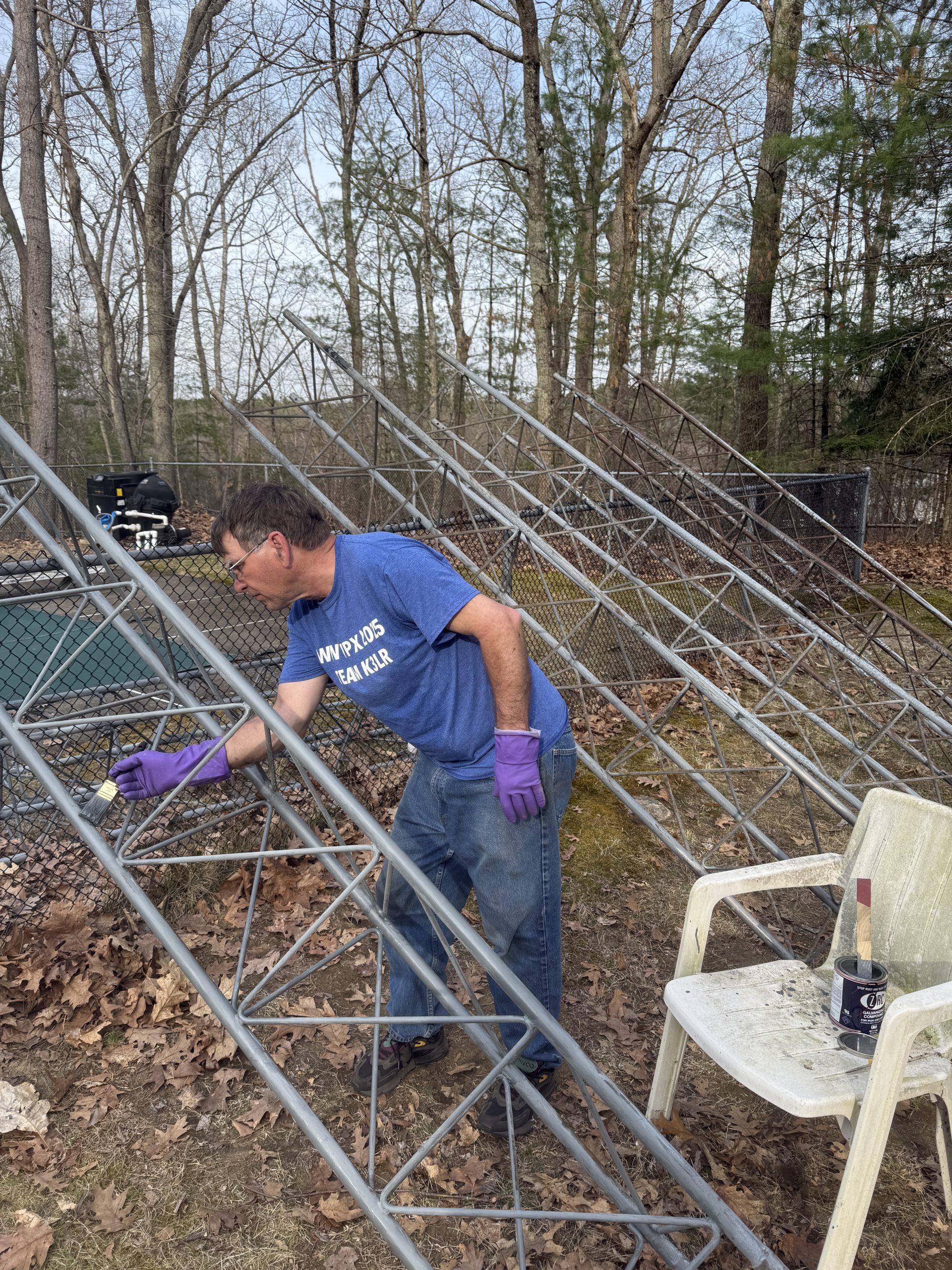
Some of the Rohn 45G sections from Tower 1 were starting to show their age, with some rust in places. With the towers on the ground and moving day still a month away, it was the perfect time to do preventative maintenance. I took advantage of a few warm days to paint some of the sections.
I purchased some ZRC 10002 Cold Galvanizing Compound from Amazon. It was almost $70 for one quart! Decided to use a brush to paint with, so I would maximize the use of this precious resource.
I had a lot of time to think during this process. I finally decided the appropriate word to describe painting a tower is “tedious.”
April 23, 2025
I spent some time hauling all the tower sections from Tower 1 down the hill, as well as rolling up all the guy wires.
I also got the temporary guy wires ready so we could move quickly when the team arrives tomorrow.
April 24, 2025
The tower crew of Mark KW1X, Martin AA1ON, and John N1PGA arrived around 10:30 am. It was a beautiful sunny day that was the perfect temperature for working outside. The bugs were starting to make an appearance, so we were very glad we had done so much of the work in March.
The C31xr is a big antenna with 14 elements and weighs almost 90 pounds. I removed the elements on each side of the boom-to-mast clamp to make some extra space. This also resulted in the antenna being very balanced, which made it easier to corkscrew around the one set of guy wires. All hands were busy, so no pictures were taken during the lowering.
It took just under 2 hours to get things rigged up and the antenna on the ground.
After the C31xr, the 5-element 6-meter beam was trivial! Although it did require me to stand on the top of the tower to reach it.
We removed the mast and the rotator and then started unstacking the tower.
This tower has a pier pin base, so it was necessary to rig some temporary guy wires before removing the set at 35′. This tower had been guyed to trees. What seemed like a good idea 30 years ago now presents some challenges.
Two of the 3 trees had died (probably from the stress). One of those was a hardwood and wasn’t going anywhere. The second was a pine tree that may have only had a few years until failure. The third tree was a larger pine that had grown around the cable holding the turnbuckle! It had grown so much that there was no way to get the turnbuckle out!
The temp guys were installed, two sections were removed, and we just had to lift the final section off the pier pin. The entire project was done around 3:30 pm. We headed off to lunch.
I returned later in the afternoon and started the disassembly of the C31xr.
Everything is now on the ground, and K5ZD/1 is off the air.
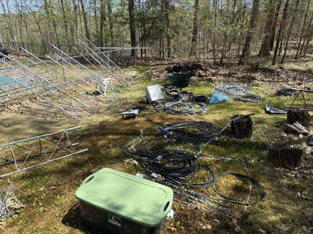
The antenna and tower staging are now almost complete.
The next task is to finish packing up the inside. It is amazing how much stuff is accumulated over the years!